Battery Pack

a battery body and battery technology, applied in the field of batteries, to achieve the effect of preventing deformation of batteries due to overvoltage or the lik

Inactive Publication Date: 2009-02-26
TDK LAMBDA CORP
View PDF4 Cites 41 Cited by
  • Summary
  • Abstract
  • Description
  • Claims
  • Application Information

AI Technical Summary

Benefits of technology

[0029]According to the present invention, a battery pack can be provided in which deformation of a battery body due to overvoltage or the like is prevented and a mechanical safety measure is taken.
[0030]Further, according to the present invention, a mechanical safety measure can be practiced utilizing the existing system.
[0031]Furthermore, according to the present invention, a secondary battery can be provided in which the battery is made to fail at an early stage of overvoltage

Problems solved by technology

The uninterruptible power supply unit mounted with the lead storage battery is required to ensure a large battery storage space and besides is extremely heavy and further has a variety of environmental problems attributable to the use of lead.

Method used


Image

  • Battery Pack
  • Battery Pack
  • Battery Pack

Examples


embodiment 1

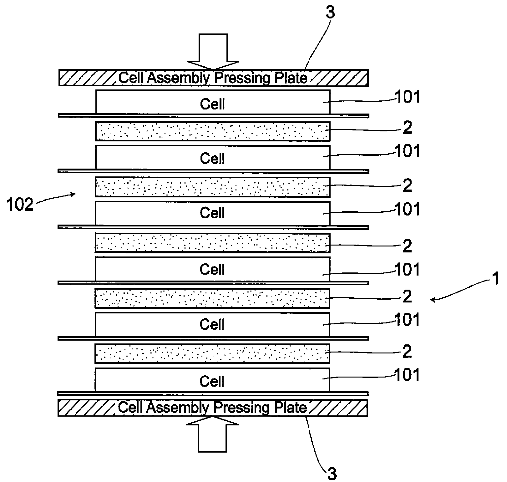
[0057]FIG. 1 is a cross-sectional view of substantial parts representing a structure of a battery pack in the present first embodiment. In a battery cell 101 acting as a battery body building up a battery pack 1, the same battery as a lithium-ion battery shown in the conventional example is employed. That is, an internal portion of the battery cell 101 is structured so that after making up a stacked structure 113 by stacking a positive-electrode material 110, a negative-electrode material 111 and a separator 112 in some layers, the stacked structure 113, together with an electrolyte, is sealed with aluminum laminates 114, 114. In the present embodiment, the battery pack 1 comprises cell assemblies 102 which act as an assembled battery body formed by stacking one on top of another in a plurality of electrically-series-connected flat-plate-like battery cells so as to attain a given voltage and capacity. In addition to this structure in the present embodiment, however, a deformation-pr...

embodiment 2

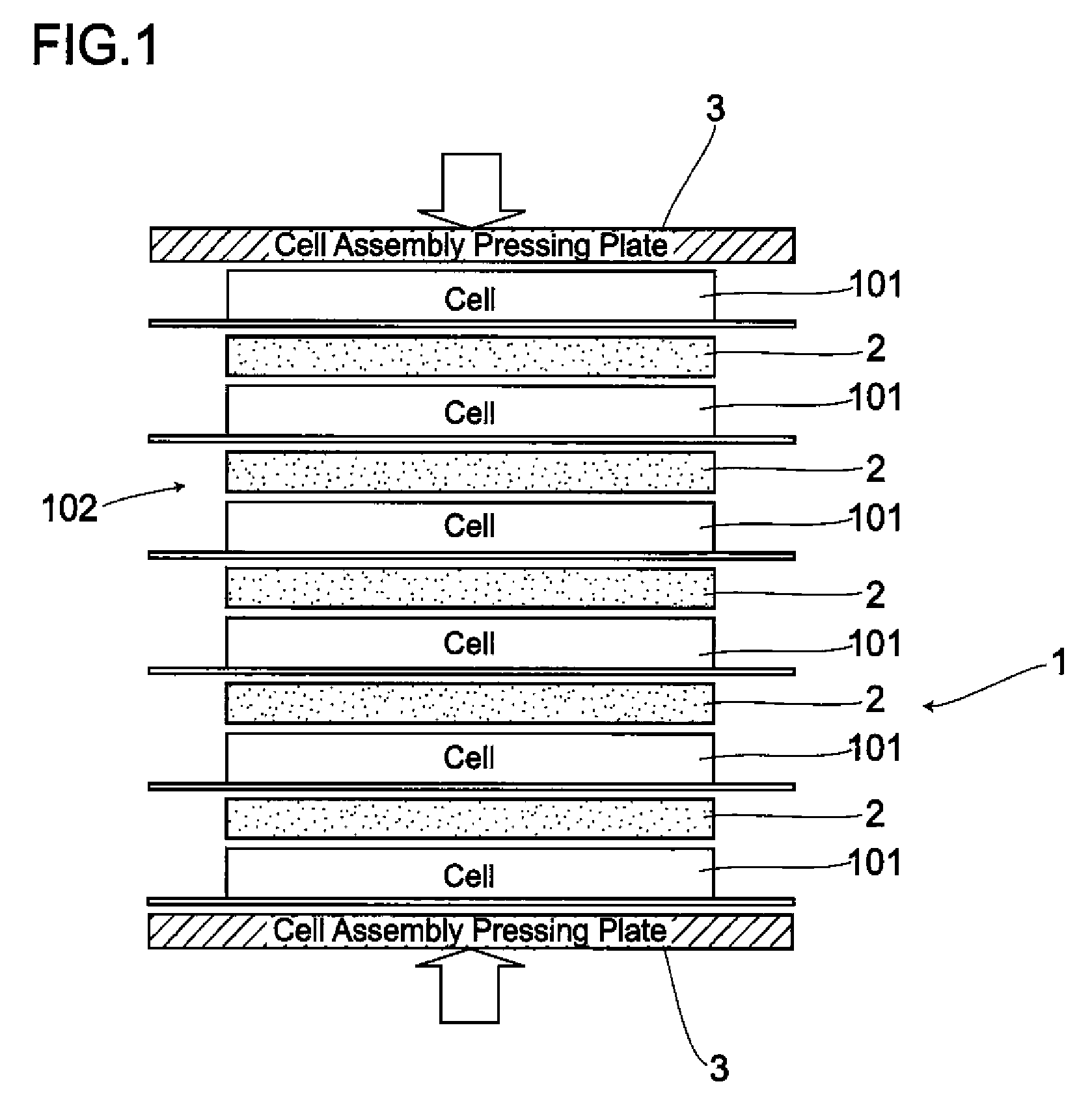
[0067]FIG. 2 is a cross-sectional view of substantial parts representing a structure of a battery pack in the present second embodiment. An essential structure of a battery cell 10 is approximately the same as that of the battery pack 1 shown in the first embodiment. That is, a cell assembly 102 makes up a battery stack formed by stacking one on top of another in a plurality of electrically-series-connected flat-plate-like battery cells so as to attain a given voltage and capacity. The deformation-preventive plate 2 is, however, inserted into a portion between each of stacked battery cells 101

[0068]In the present second embodiment, a boxy pack case 11 as a deformation-preventive means is employed in place of the cell assembly pressing plates 3, 3. The boxy pack case 11 is formed in a somewhat lower shape than the cell assemblies 102 into which the deformation-preventive plates 2 are inserted. When housing the cell assembly 102 inside the boxy pack case 11, the cell assembly 102 is p...


PUM

PropertyMeasurementUnit
thermal insulating propertyaaaaaaaaaa
thermal conductionaaaaaaaaaa
internal pressureaaaaaaaaaa

Abstract

A battery cell 101 has an internal structure where after building up an assembled unit by stacking positive-and negative-electrode materials 110, 111 and a separator 112 in some layers, the assembled units, together with an electrolyte, are sealed with aluminum laminates 114, 114. The battery pack 1 comprises cell assemblies 102 formed by stacking one on top of another in a plurality of the battery cells 101. A deformation-preventive plate 2 is inserted into a portion between each of the battery cells 101 stacked. The cell assemblies 102 inserted by the deformation-preventive plates 2 between each of the battery cells are pressed by cell assembly pressing plates 3, 3 from the upper and lower sides of the battery assemblies. The cell assemblies 102 are pressed by the cell assembly pressing plates 3, 3 to be subjected to some degree of pressure. Hence, the cell assemblies 102 expand not largely to be maintained as an approximately the same form as that at a normal time.

Description

TECHNICAL FIELD[0001]The present invention relates to a battery pack such as that of a lithium-ion secondary battery or the like which is made available for an electric power supply for a wide variety of electronic equipment.BACKGROUND ART[0002]In general, in an uninterruptible power supply unit requiring a backup electric power supply, while an input voltage from a commercial alternating-current power supply is being normally generated, a direct-current or alternating voltage which is required for load is supplied from a master electric power supply of an electric source body acting as electronic equipment to a load with a secondary battery being charged via the master electric power supply. While, when the input voltage has dropped markedly or power failure has occurred, a secondary battery acting as a backup electric power supply supplies electric power from the master electric power supply to the load without interruption. The secondary battery employed here has been conventiona...

Claims


Application Information

Patent Timeline
Patent Type & Authority Applications(United States)
IPC IPC(8): H01M2/12H01M10/50H01M2/10H01M2/02H01M50/211
CPCH01M2/1077H01M2/1241H01M10/0413H01M10/0468H01M10/5087H01M10/5032H01M10/5053H01M10/5055H01M10/5004H01M10/647H01M10/6555H01M10/6554H01M10/613H01M10/658Y02E60/10H01M50/3425H01M10/0481H01M50/211
Inventor NAKAZAWA, HIROSHI
Owner TDK LAMBDA CORP
Why Eureka
Try Eureka