Head-coupled holder for living body optical measurement

a technology of optical measurement and head-coupling holder, which is applied in the field can solve the problems of inability to conduct a precise evaluation, inability to withstand the measurement for a long time, and strong pressure on so as to improve the measurement precision of living body optical measurement, improve the comfort of the person to be examined who wears the holder, and improve the effect of the measurement precision

Active Publication Date: 2009-02-26
HITACHI LTD
View PDF6 Cites 8 Cited by
  • Summary
  • Abstract
  • Description
  • Claims
  • Application Information

AI Technical Summary

Benefits of technology

[0005]An object of the present invention is to provide a head-coupled holder for living body optical measurement which securely brings a light irradiation / light detection module in close contact with a scalp, and does not give the feeling of an excessive pressure to the person to be examined in order to enable precise living body optical measurement to be realized for all of persons to be examined and in all of measurement configurations.
[0008]According to the present invention, the light irradiation portion of the light irradiation module or the light introduction portion of the light detection module can be excellently brought in close contact with the scalp without applying an excessive force to the head of the person to be examined, thereby improving the measurement precision of the living body optical measurement. Also, because the uncomfortable feeling of the person to be examined who wears the holder can be also remarkably reduced, it is possible to wear the holder for a long time, wear the holder in a state close to the everyday life, and wear the holder by the person to be examined such as an older person, an infant, or a young child, to thereby remarkably enlarge the measurable range of the living body optical measurement.

Problems solved by technology

When those conditions cannot be satisfied, a ratio (S / N ratio) of the signal light to the noise light cannot be held to a high value, thereby making it impossible to conduct a precise evaluation.
However, there is a case in which when the module is fixed to the head with the strong force, the person to be examined may feel a strong pressure, and cannot withstand the measurement for a long time.
There is the possibility that this causes an obstacle to the measurement in everyday life or a condition close to the everyday life.
Also, the person to be examined with old age, an infant, and a young child may not withstand the wear of the module due to the pressure feeling, and therefore the measurement per se cannot be conducted.

Method used


Image

  • Head-coupled holder for living body optical measurement
  • Head-coupled holder for living body optical measurement
  • Head-coupled holder for living body optical measurement

Examples


first embodiment

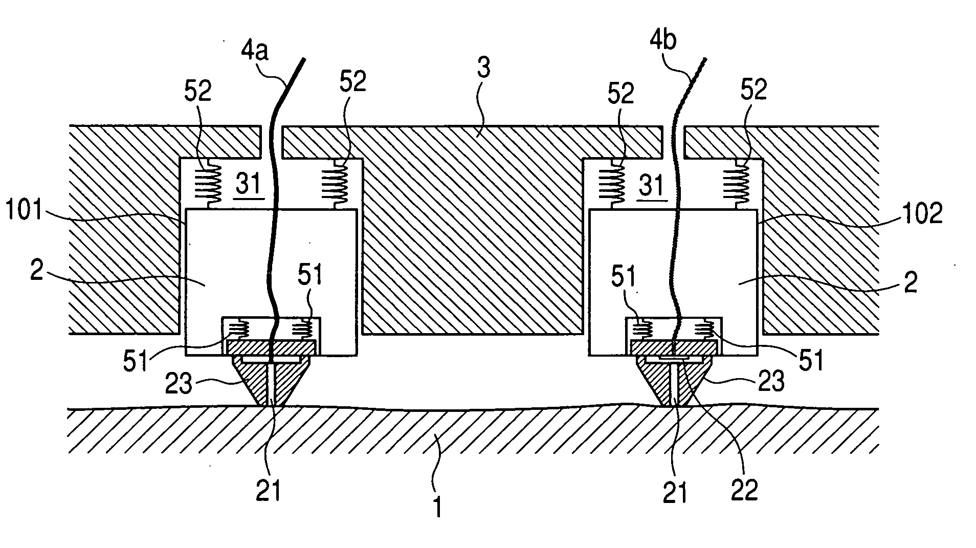
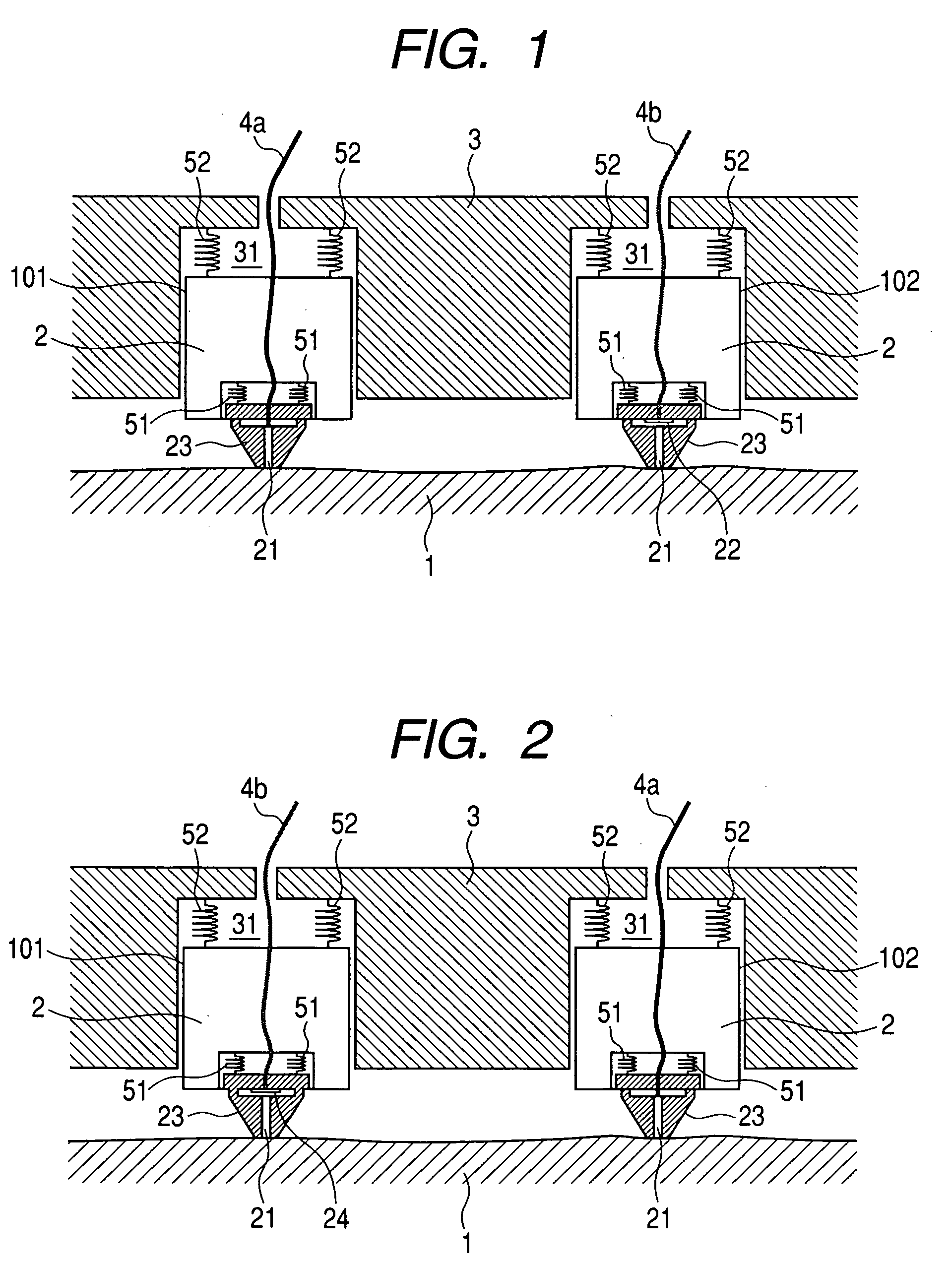
[0023]A first embodiment of the present invention will be described with reference to FIGS. 1 and 2. FIG. 1 schematically shows a head-coupled holder for living body optical measurement having a light irradiation module 101 and a light detection module 102 in a living body optical measuring device. The numbers of light irradiation modules and light detection modules are one in FIG. 1, respectively, but plural modules can be provided, respectively. In this example, the light detection module 102 shown on a right side of the drawing will be described. In the drawing, reference numeral 1 denotes a head (scalp) of a person to be examined, 2 is a package of a module, 3 is a holder that fixes the package 2, and 4b is a cable for connecting the module and a control unit module. The package 2 is made of rigid resin such as vespel (R) (polyimide), and inserted into a package insertion hole 31 that is defined in a lower surface of the holder 3. The lower portion of the package 2 is fitted wit...

second embodiment

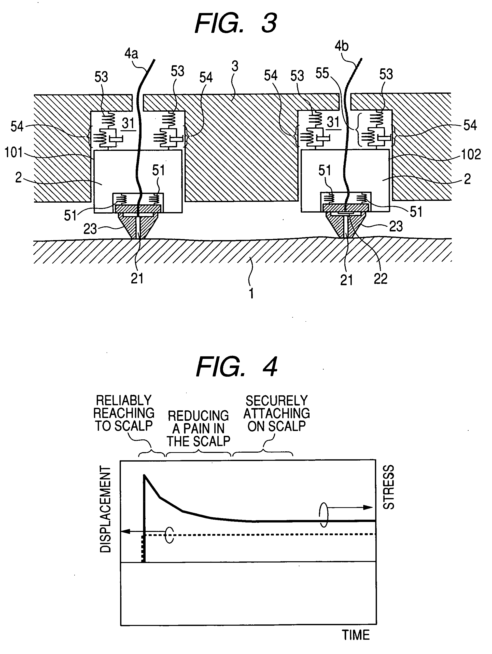
[0031]Now, a description will be given of a second embodiment of the present invention with reference to FIGS. 3 to 5. FIG. 3 schematically shows a part of a head-coupled holder for living body optical measurement in a living body optical measuring device with the same configuration as that of FIG. 1. A difference from FIG. 1 resides in that a portion that connects the package 2 and the holder 3 is formed of a member 55 that connects an elastic body 53 and a viscoelastic body 54 in series.

[0032]The viscoelastic body is made of a material having both properties of viscosity and elasticity. More specifically, a creep phenomenon in which the viscoelastic body is gradually deformed with application of a certain stress, and a stress relaxation phenomenon in which the stress is gradually reduced when the viscoelastic body is displaced to some degree are actions specific to the viscoelastic body. On the other hand, the elastic body is made of a material having a property that produces a re...

third embodiment

[0037]Now, a description will be given of a third embodiment of the present invention with reference to FIGS. 6 and 7. FIG. 6 shows a structure in which a portion that connects the package 2 and the holder 3 is formed of a member 55 that connects the elastic body 53 and the viscoelastic body 54 in series. The contactor 23 and the package 2 are rigidly fixed to each other.

[0038]Similarly, the structure shown in FIG. 6 is capable of realizing a change in the pressure with time as shown in FIG. 4. That is, the pressure becomes relatively high immediately after the holder has been worn on the head, which surely brings the leading end of the contactor 23 in each of the modules in close contact with the scalp. Thereafter, the pressure is gradually attenuated to reduce a load on the person to be examined. Further, the pressure is held to a given pressure value, thereby preventing the worn holder 3 from being uncoupled. Accordingly, the use of the holder according to this embodiment enables...


PUM


Abstract

A head-coupled holder for living body optical measurement that securely brings a light irradiation module and a light detection module in close contact with a scalp, and gives the person to be examined no excessive pressure feeling. Each of the light irradiation module and the light detection module includes a contactor having a contact portion that comes in contact with a scalp of the person to be examined at a leading end thereof, and exposes a leading end of a light guide to the contact portion to form the light guide, and a package having a lower portion to which the contactor is attached. The contactor is fixed to the lower portion of the package through an elastic body, and the package is fixed to an inner upper wall of the insertion hole with a series structure of the elastic body and the viscoelastic body.

Description

CLAIM OF PRIORITY[0001]The present application claims priority from Japanese patent application JP 2007-214919 filed on Aug. 21, 2007, the content of which is hereby incorporated by reference into this application.FIELD OF THE INVENTION[0002]The present invention relates to a living body optical measurement that measures an internal state of a living body by the aid of a light, and more particularly to a head-coupled holder for living body optical measurement for measuring a brain function by analysis of a light intensity that that passed through a head.BACKGROUND OF THE INVENTION[0003]As means for measuring the brain function of a human body, there has been developed an optical topographic technique that analyzes the intensity of a return near-infrared light which has been applied to a part of the head and has then passed through the head to two-dimensionally display a blood distribution of a cerebral cortex. The above technique proves the correspondence of the motor functions of a...

Claims


Application Information

Patent Timeline
Patent Type & Authority Applications(United States)
IPC IPC(8): A61B5/00
CPCA61B5/0059A61B5/1455A61B2562/046A61B2562/0233A61B5/6814
Inventor KIGUCHI, MASASHIMATSUSHIMA, NAOKIATSUMORI, HIROKAZU
Owner HITACHI LTD
Why Eureka
Try Eureka