

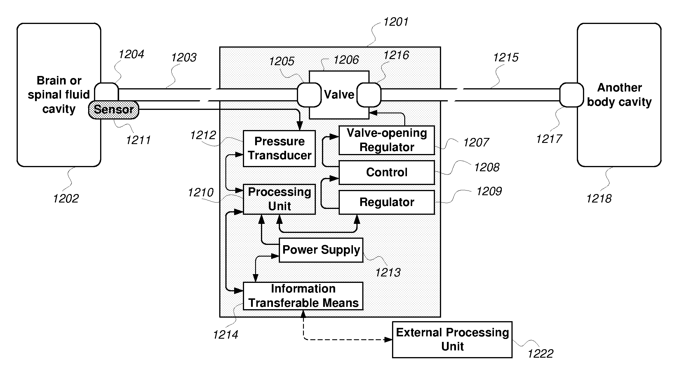
System for use in draining fluid from a brain or spinal fluid cavity unto another body cavity of a human being
a technology for draining fluid and brain, which is applied in the field of system for draining fluid from brain or spinal fluid cavity to another body cavity of human being, can solve the problems of no or minimal opportunities for quality control and the challenge is even greater, and achieve the effect of quick diagnosis and intervention
- Summary
- Abstract
- Description
- Claims
- Application Information
AI Technical Summary
Benefits of technology
Problems solved by technology
Method used
Image

Examples
Embodiment Construction
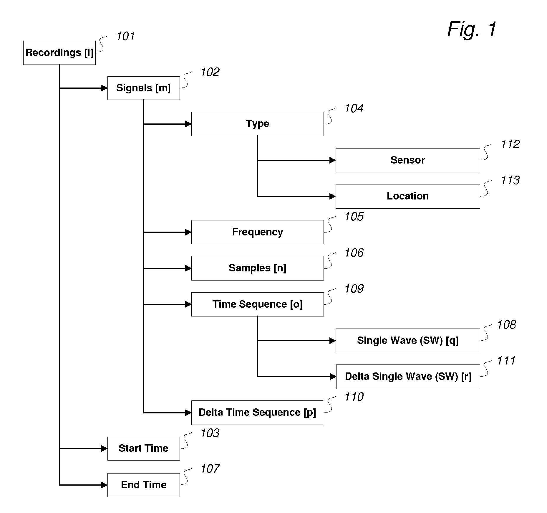
[0134]In FIG. 1 is shown an overview of notation and relationships related to continuous pressure signals, as used according to this invention. A recording 101 is one or more simultaneous signals 102 derivable from locations inside or outside a human or animal body or body cavity, each of said signals 102 having identical time reference, though it is not a requirement that start time 103 is identical for all signals of a recording. Each signal has the following attributes: type 104, frequency 105, and actual samples 106. Given these values, end time 107 can be calculated. According to this invention a specific sampling frequency 105, is not given. For single pressure wave analysis, it has been found that sampling frequencies of 100 to 200 Hz are useful. The notation List[x] is a reference to an element within an ordered list. With reference to FIG. 1, some examples are given:
[0135]The notation Recording [l].Signal [m].Time Sequence [o].Single Wave [q]) denotes a specific Single Wave...
PUM
 Abstract
Description
Claims
Application Information