Supercharge Your Innovation With Domain-Expert AI Agents!

Hierarchical cache memory system

Inactive Publication Date: 2009-02-26
RENESAS ELECTRONICS CORP
View PDF9 Cites 18 Cited by
  • Summary
  • Abstract
  • Description
  • Claims
  • Application Information

AI Technical Summary

Benefits of technology

[0012]A hierarchical cache memory system comprising: a first cache system having a first cache memory storing first data, said first cache system further having a first cache controller; and a second cache system coupled to said first cache system and having a second cache controller, said first cache system transferring said first data toward said external memory through said second cache system, wherein said first cache controller controls said first cache system to perform a first transfer operation in which said first cache controller obtains said first data from said first cache memory and transfers said first data to said second cache system, wherein said second cache controller controls said second cache system to perform a second transfer operation in which said second cache controller receives said first data from said first cache system and transfers said first data toward said external memory, wherein said first and second transfer operations are performed at least partially in parallel. According to the present invention, since the output of the first dirty data from the first cache memory is produced in parallel with the output of the first dirty data from the second cache memory, it is made possible to increase the speed of the write-back process in the hierarchical cache memory.

Problems solved by technology

In a computer system having cache memory between a central processing unit (CPU) which can operate at high-speed and external memory (main memory) which has a large capacity and operates at low speed, dirty data, which are not written into the external memory by the CPU are caused while the data are already written into the cache memory by the CPU for updating.
This is because all the data stored in the cache memory are lost due to the stop of the power supply to the cache memory.

Method used


Image

  • Hierarchical cache memory system
  • Hierarchical cache memory system
  • Hierarchical cache memory system

Examples


first embodiment

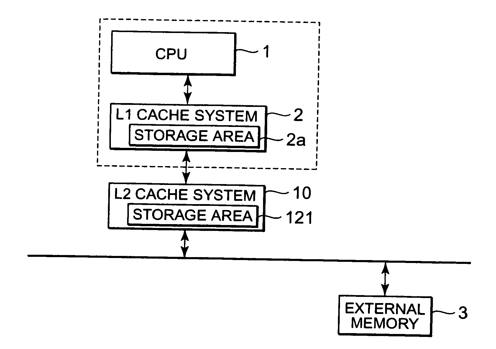
[0030]FIG. 5 is a block diagram showing a detailed configuration of the L2 cache system according to the present invention. Furthermore, the operation of the L1 cache system can be set to be controlled by the controller (cache controller) being in the L1 cache system, for example. It is hereunder assumed that the operation performed by the L1 cache system is controlled by the cache controller. With reference to FIGS. 1 and 5, the L1 cache system receives an instruction from the CPU 1, and outputs dirty data stored in the storage area 2a to a buffer 122 included in a cache memory circuit 12 via a CPU bus interface (CPU BUS I / F) and outputs an Index value of a datum outputted to the buffer 122 to an address register 19. The CPU 1 outputs a minimum Index value held by the storage area 2a to a start address register 14 when the L1 cache system executes the write-back process, and also outputs a maximum Index value similarly held by the storage area 2a to an end address register 15. More...

third embodiment

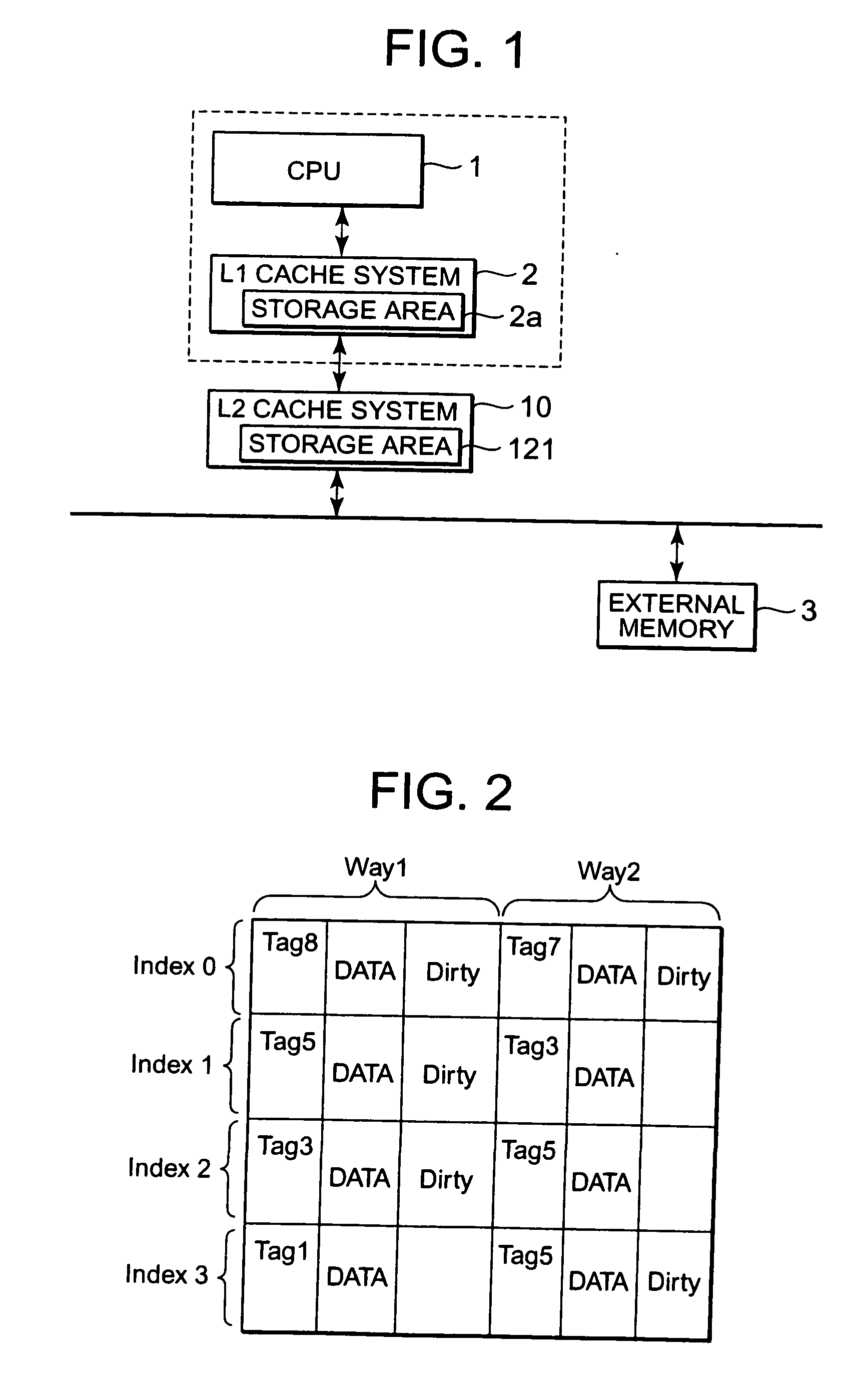
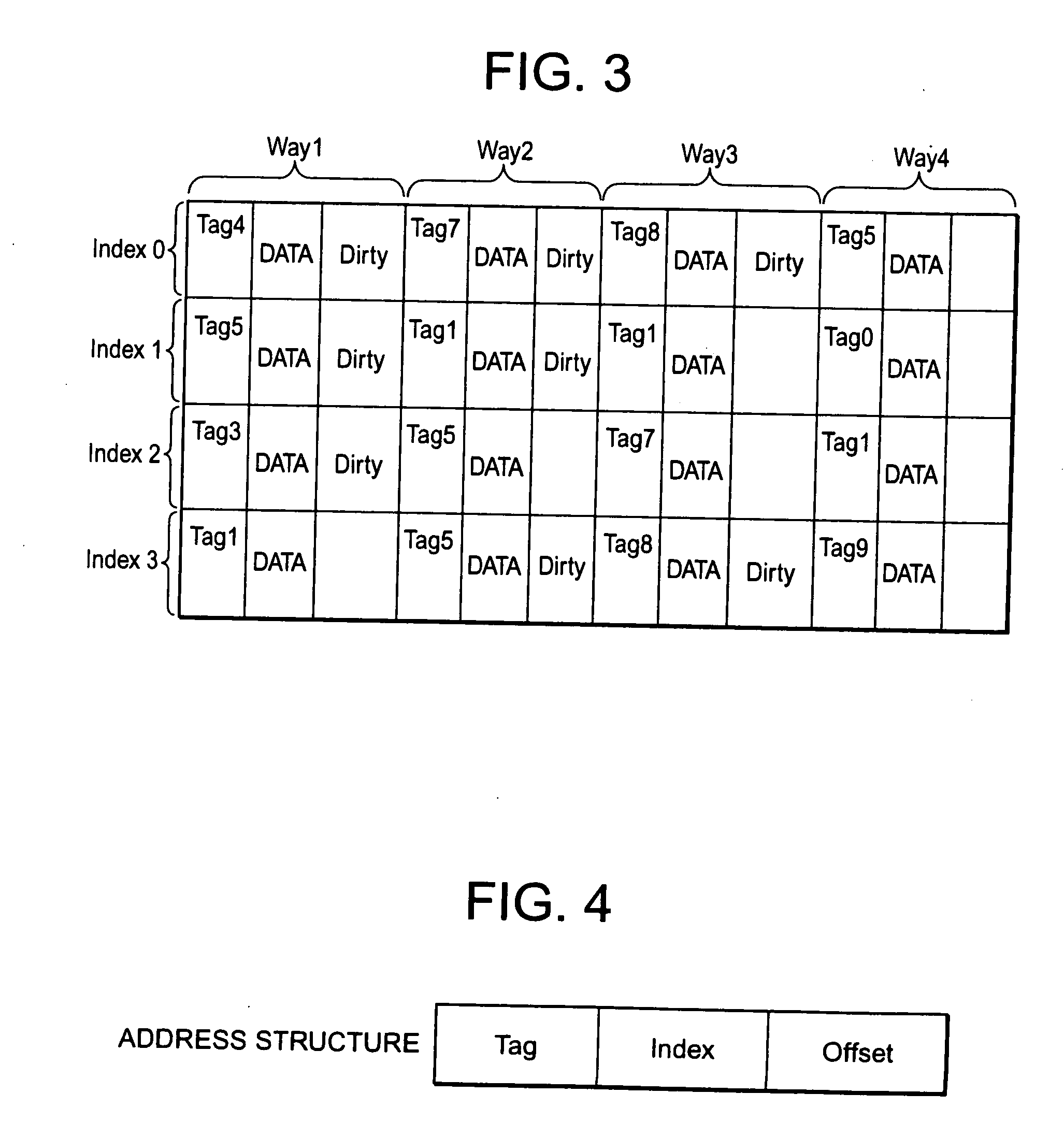
[0072]The controller of the L1 cache system 2 outputs the dirty data stored in the storage area 2a to the L2 cache system 10 in the order of ascending Index values. In other words, with reference to FIGS. 2 and 3, the controller of the L1 cache system 2 sequentially outputs to the L2 cache system 10 starting from the dirty data having the Index value 0 to the dirty data having the Index value 3. However, in the third embodiment, data outputted by the controller of the L1 cache system 2 varies depending on the Tag value. The start address register 14 and the end address register 15 included in the L2 cache system 10 store the Tag values 4 and 7, but the controller of the L1 cache system 2, too, recognizes the Tag values 4 and 7 from the CPU 1 beforehand. In accordance with the Tag values 4 and 7, the controller of the L1 cache system 2 firstly outputs to the L2 cache system 10 dirty data having the Index value 0 in a range of the Tag values 4 to 7. Next, the controller of the L1 cach...


PUM


Abstract

A hierarchical cache memory system having first and second cache memories includes: a controller which outputs dirty data stored in the first cache memory to write back to a main memory; and a controller which processes the write-back to the main memory of the dirty data outputted from the first cache memory in parallel with the write-back to the main memory of dirty data stored in the second cache memory.

Description

BACKGROUND OF THE INVENTION[0001]1. Field of the Invention[0002]The present invention relates to a hierarchical cache memory system, and particularly relates to a hierarchical cache memory system having a write-back controller.[0003]2. Description of Related Art[0004]In a computer system having cache memory between a central processing unit (CPU) which can operate at high-speed and external memory (main memory) which has a large capacity and operates at low speed, dirty data, which are not written into the external memory by the CPU are caused while the data are already written into the cache memory by the CPU for updating. Here, when the CPU stops a clock signal supplied to the CPU and shifts to sleep mode by turning off the power supplied to the cache memory, the CPU is required to write back all the dirty data stored in the cache memory to the external memory. This is because all the data stored in the cache memory are lost due to the stop of the power supply to the cache memory....

Claims


Application Information

Patent Timeline
IPC IPC(8): G06F12/08
CPCG06F12/0897G06F12/0804G06F12/08
Inventor MIWA, HIDEYUKIYAMADA, TAMOTSU
Owner RENESAS ELECTRONICS CORP
Features
  • R&D
  • Intellectual Property
  • Life Sciences
  • Materials
  • Tech Scout
  • Unparalleled Data Quality
  • Higher Quality Content
  • 60% Fewer Hallucinations
Learn More