Digital Broadcast Receiving Apparatus
- Summary
- Abstract
- Description
- Claims
- Application Information
AI Technical Summary
Benefits of technology
Problems solved by technology
Method used
Image
Examples
first exemplary embodiment
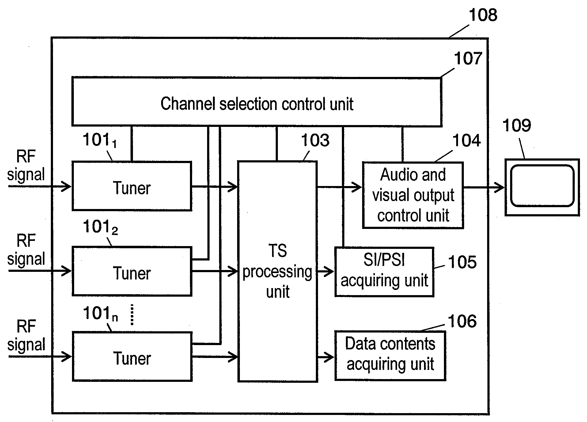
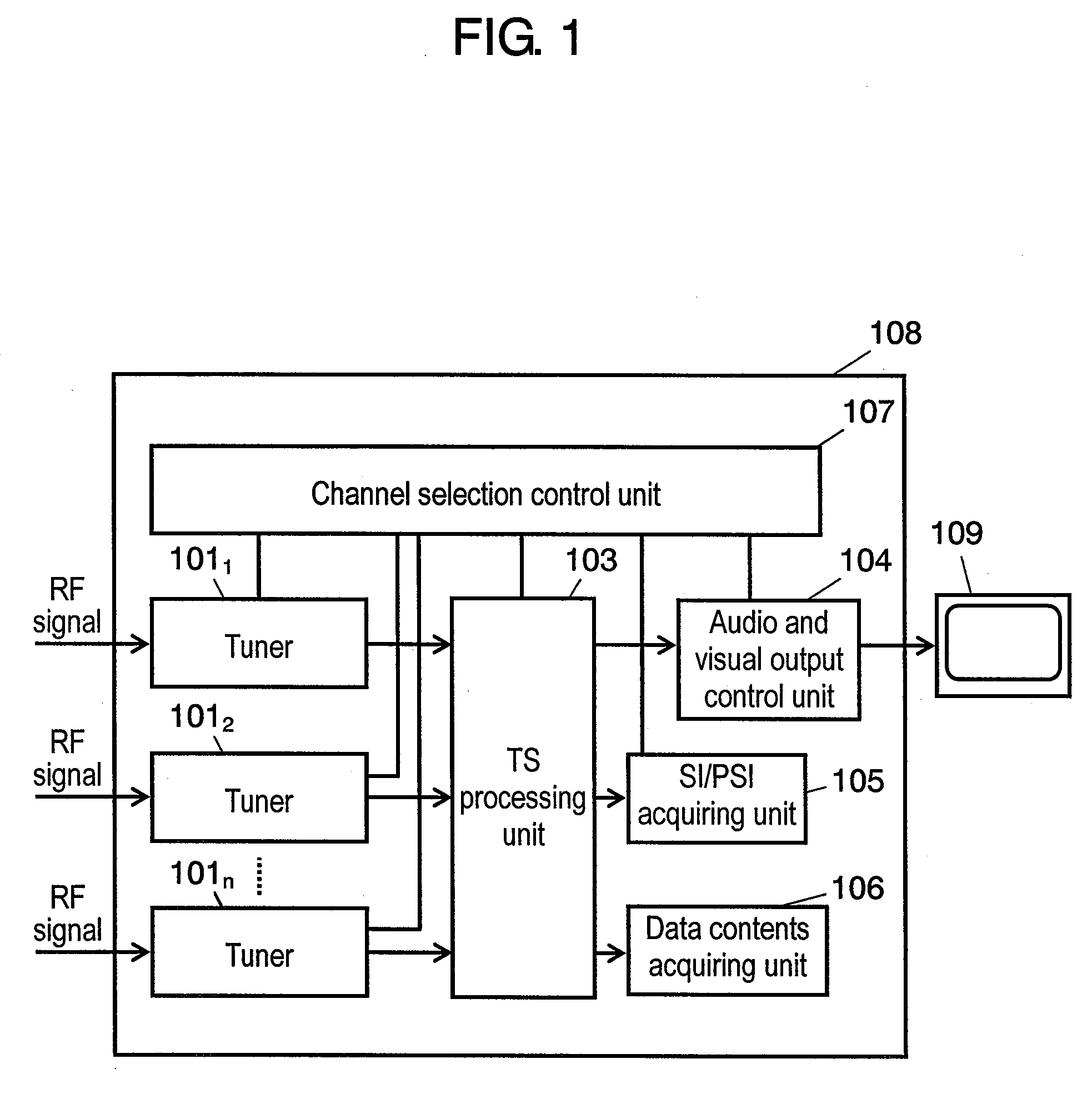
[0033]FIG. 1 is a block diagram illustrating the makeup of a digital broadcast receiving apparatus according to the first embodiment of the present invention. In FIG. 1, digital broadcast receiving apparatus 108 is equipped with n (n is a natural number 2 or larger) tuners 1011 through 101n, TS processing unit 103, SI / PSI acquiring unit 105, data contents acquiring unit 106, audio and visual output control unit 104, and channel selection control unit 107. Tuners 1011 through 101n are supplied with a radio-frequency (described as RF hereinafter) signal to receive digital broadcast waves. TS processing unit 103 processes at least two TSes demodulated by tuner 1011 to 101n.
[0034]SI / PSI acquiring unit 105 extracts and acquires service information from the TS processing unit. Data contents acquiring unit 106 caches data contents. Audio and visual output control unit 104 processes plural audio and visual data simultaneously or alternately by switching to output to display unit 109. Channe...
second exemplary embodiment
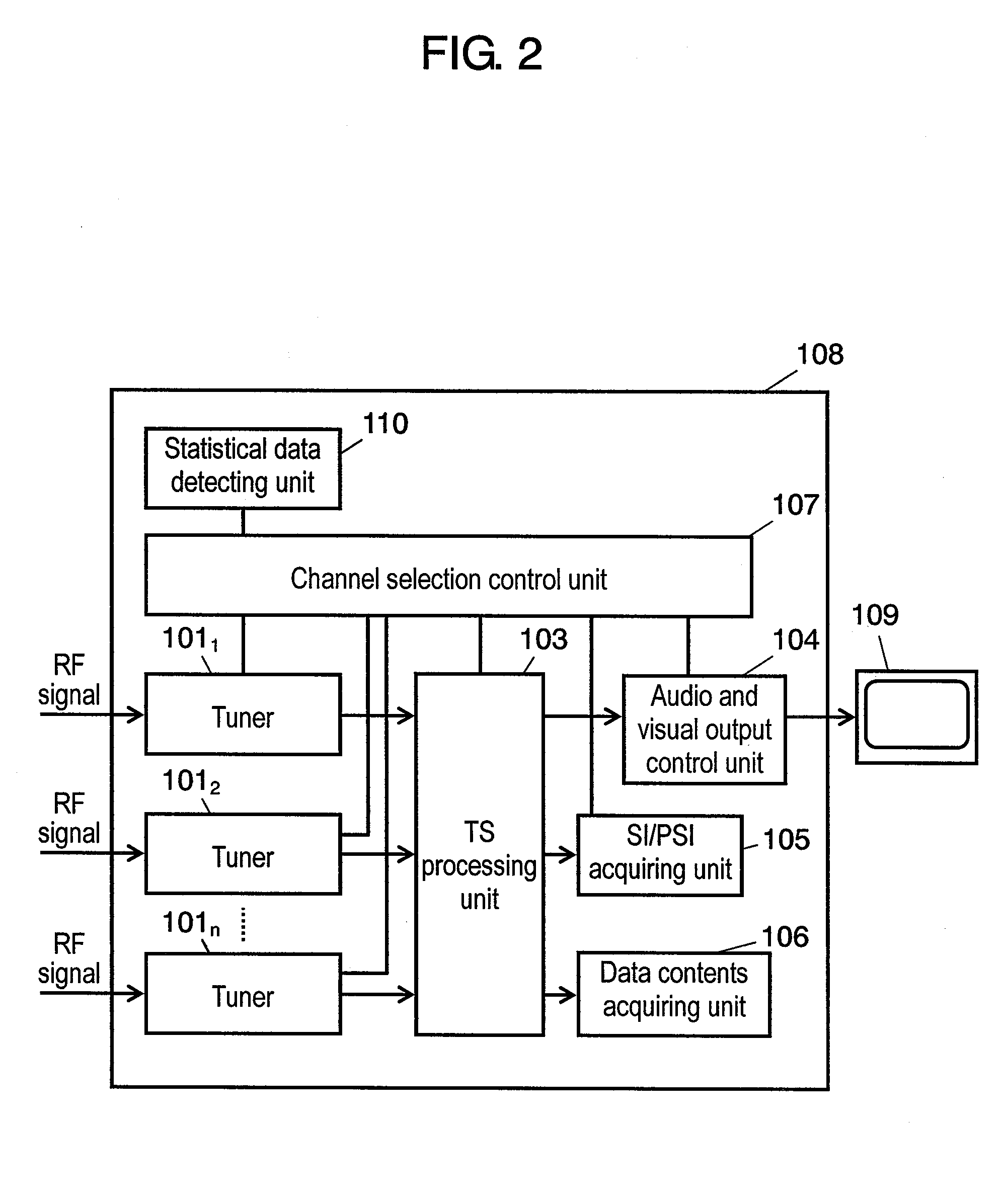
[0037]FIG. 2 is a block diagram illustrating the makeup of a digital broadcast receiving apparatus according to the second embodiment of the present invention. In FIG. 2, a component same as that in FIG. 1 is given the same reference mark to omit its description. In this embodiment, statistical data detecting unit 110 is provided that detects statistical data related to reception of digital broadcast waves. In a digital broadcast receiving apparatus with the above-described makeup, a description is made using FIG. 2 for how to increase the speed of zapping (e.g. changing the channel to a higher number continuously while commercial messages are broadcast).
[0038]The assumption is made that this is a digital broadcast receiving apparatus in which the channel changes from channel A to channel B, from channel B to channel C, and from channel C to channel D when the user changes the channel to a higher number while viewing channel A through tuner 1011. At this moment, if the channel-up bu...
third exemplary embodiment
[0042]FIG. 3 is a block diagram illustrating the makeup of a digital broadcast receiving apparatus according to the third embodiment of the present invention. In FIG. 3, a component same as that in FIG. 1 is given the same reference mark to omit its description. In this embodiment, viewing pattern detecting unit 111 is provided that detects user's viewing patterns. In a digital broadcast receiving apparatus with the above-described makeup, a description is made using FIG. 3 for a channel selection prediction algorithm based on user's viewing patterns
[0043]The assumption is made that the user viewed channel B and is now viewing channel A, through tuner 1011. Viewing pattern detecting unit 111 stores user's previous viewing information. Specifically, the information includes a viewed channel, a clock time when switching to the channel to be viewed, and a clock time when ending viewing the channel.
[0044]Viewing pattern detecting unit 111 can obtain information related to a clock time f...
PUM
 Abstract
Description
Claims
Application Information
 - R&D
- Intellectual Property
- Life Sciences
- Materials
- Tech Scout
- Unparalleled Data Quality
- Higher Quality Content
- 60% Fewer Hallucinations
Browse by: Latest US Patents, China's latest patents, Technical Efficacy Thesaurus, Application Domain, Technology Topic, Popular Technical Reports.
© 2025 PatSnap. All rights reserved.Legal|Privacy policy|Modern Slavery Act Transparency Statement|Sitemap|About US| Contact US: help@patsnap.com


