Cavity wall spacer, building structure and method

Inactive Publication Date: 2009-03-05
SURECAV
View PDF11 Cites 2 Cited by
  • Summary
  • Abstract
  • Description
  • Claims
  • Application Information

AI Technical Summary

Benefits of technology

[0009]Accordingly, the first aspect provides at least one projection, and more typically a plurality of projections, each having a recessed channel. The recessed channel or groove helps to prevent the passage of moisture along the length of the projection which provides an efficient way of preventing moisture traveling between the two leaves of the wall. Also, a recessed channel reduces the amount of moisture which drips into the cavity since the moisture is more likely to track back along the surface of the projection. Additionally, providing a recessed channel ensures no external obstruction on the projections which helps to achieve a significantly improved stacking density. Furthermore, the projections are less prone to any damage since there are no external protrusions.
[0011]In one embodiment, the recessed channel is operable to cause the moisture collected therein to gather at a moisture-release point. Hence, the channel acts as a conduit along which the accumulated moisture may flow to a moisture-release point. It will be appreciated that in practice small droplets will accumulate in the recessed channel which will combine into larger droplets which, once a sufficient mass has been achieved, will overcome surface tension and will flow along the recessed channel under gravity to the underside of the recessed channel when installed in the cavity. The underside of the channel when installed in the cavity may provide two moisture-release points, one at each side of the recessed channel.
[0020]In one embodiment, each projection is hollow. It will be appreciated that providing a hollow projection increases the stacking density.

Problems solved by technology

The first aspect recognizes that a problem with the existing cavity wall spacers is that they either have no moisture barrier rib, in which case more moisture than may be desirable can track along the length of the projection from the external leaf to the internal leaf, or they have a moisture barrier rib and this causes moisture to gather and then drip into the cavity in the vicinity of the moisture barrier rib.
Also, a problem with arrangements having moisture barrier ribs is that when the sheets of cavity wall spacers are stacked for storage or transport the packing density of the sheets is low since the barrier rib prevents close stacking of the sheets.
Furthermore, these barrier ribs can become damaged.

Method used


Image

  • Cavity wall spacer, building structure and method
  • Cavity wall spacer, building structure and method
  • Cavity wall spacer, building structure and method

Examples


Embodiment Construction

[0039]In the following description, numerous specific details are set forth in order to provide a more thorough description of the present invention. It will be apparent, however, to one skilled in the art, that the present invention may be practiced without these specific details. In other instances, well-known features have not been described in detail so as not to obscure the invention.

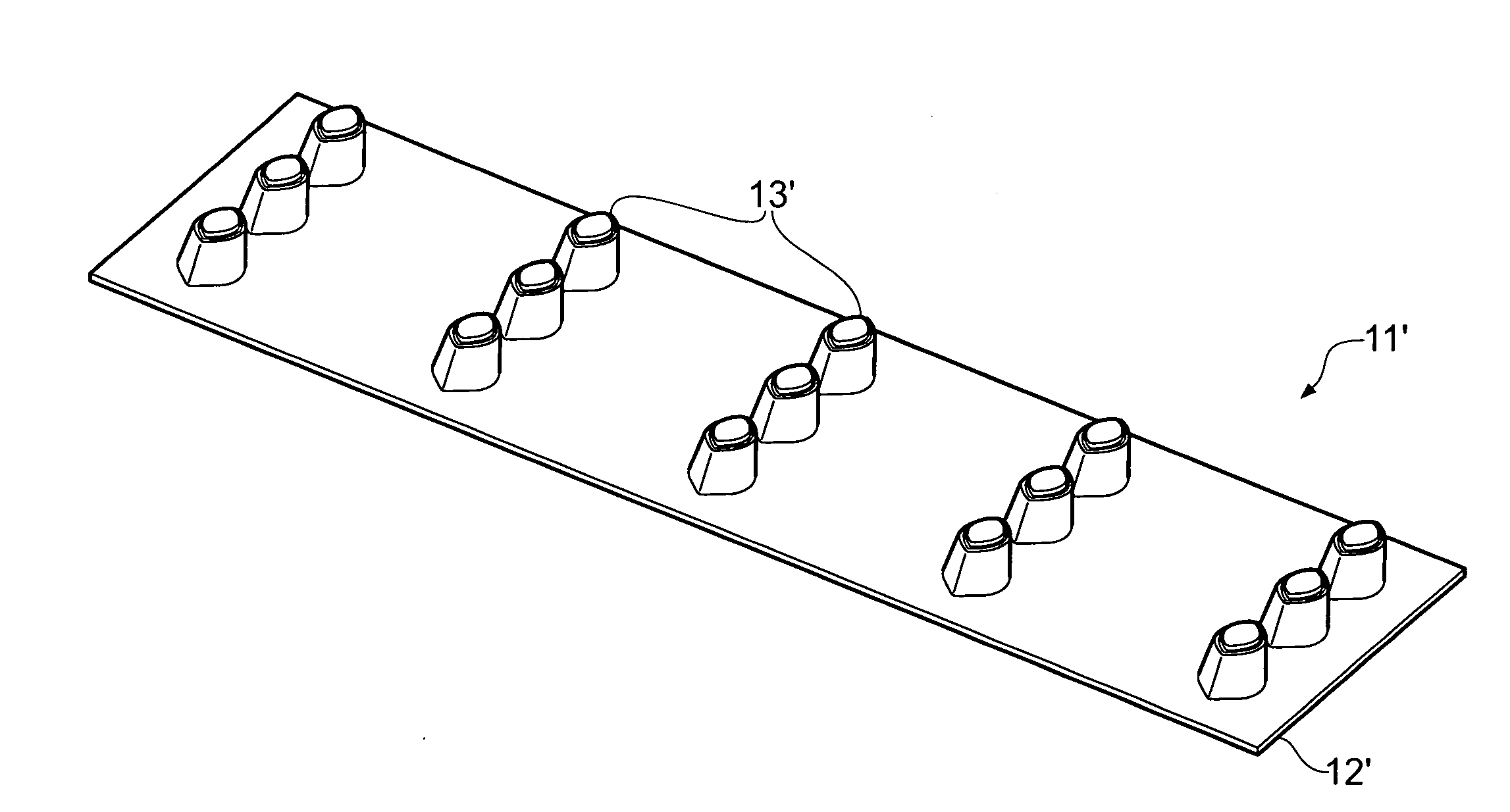
[0040]For a cavity wall to effectively work as a moisture barrier, the cavity or gap should not be bridged in any way. A cavity wall spacer may be used to inhibit the transfer of moisture from the exterior leaf to the interior leaf in one or more embodiments. GB 2 388 614, which is incorporated herein by reference, illustrates an example of a spacer that may be used in this manner. The cavity wall spacer disclosed herein, comprises a novel configuration which provides various advantages which will be apparent from the description below.

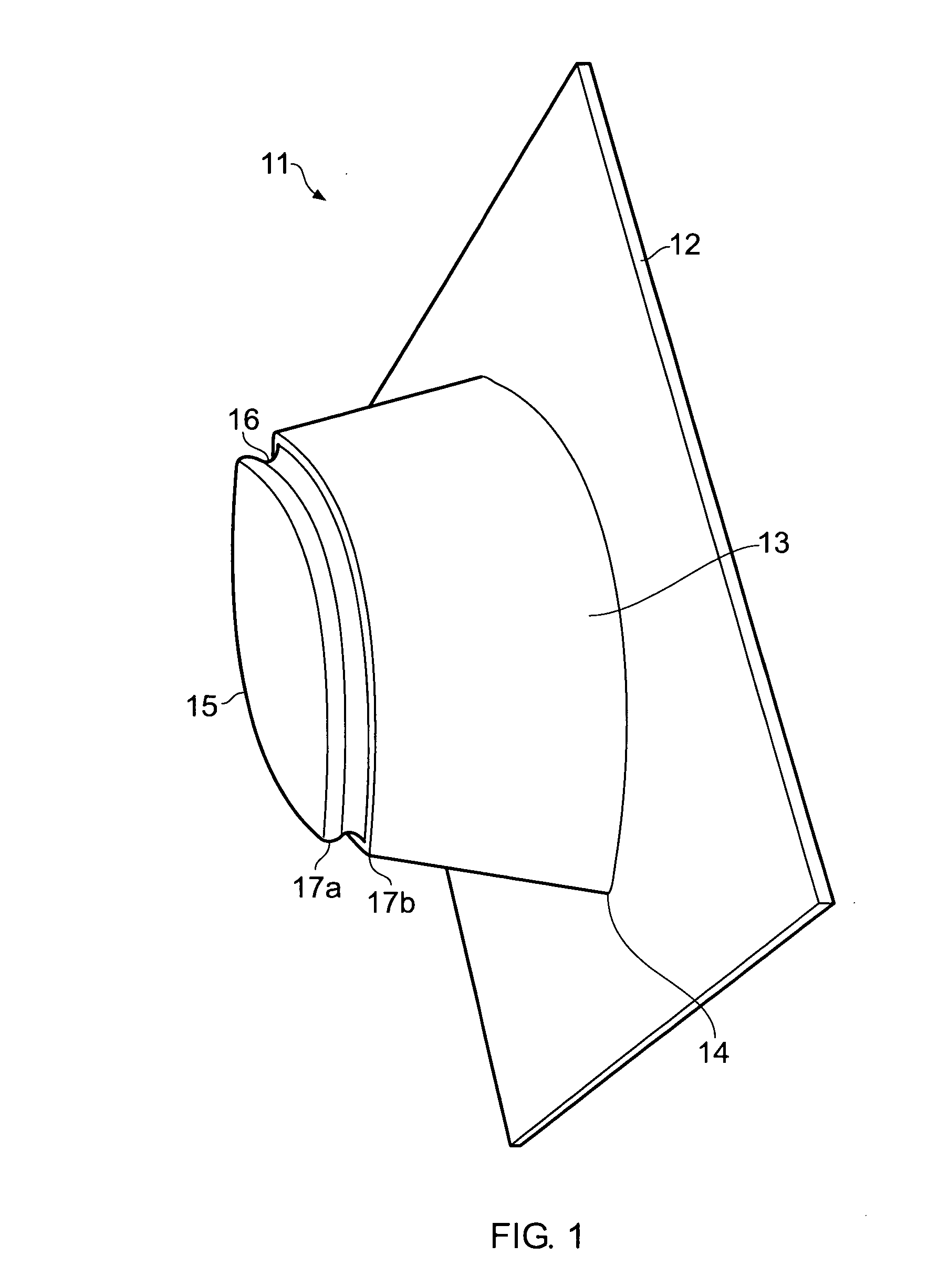
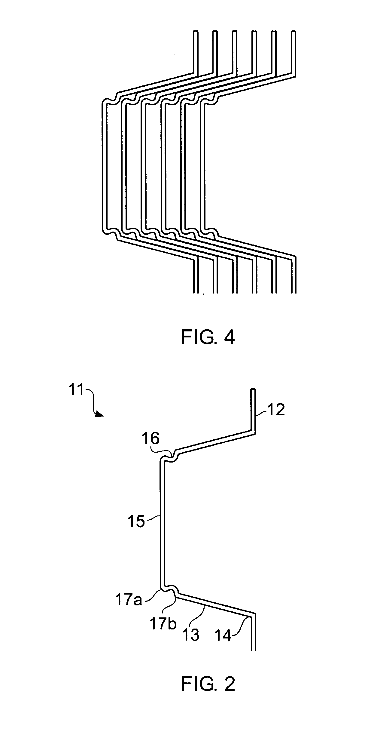
[0041]Referring to FIG. 1, there is shown a cavity wall spacer,...


PUM


Abstract

A cavity wall spacer, building structure, and method are disclosed. The cavity wall spacer determines a separation of building elements of two leaves of a wall. The cavity wall spacer comprises: a support body; and a plurality of spaced projections upstanding from the support body and operable to extend across a cavity between the leaves, each projection having a recessed channel operable to inhibit transfer of moisture from one end of each projection to another. The recessed channel prevents the passage of moisture along the length of the projection to prevent moisture from traveling between the two leaves of the wall, and reduces the amount of moisture which drips into the cavity. The recessed channel has no external obstructions and thus allows significantly improved stacking density. The projections are less prone to any damage since there are no external protrusions.

Description

CROSS-REFERENCE TO RELATED APPLICATION[0001]This application claims priority to European Patent Application No. 07253268.2 entitled Cavity Wall Spacer, Building Structure, and Method, filed Aug. 20, 2007.BACKGROUND OF THE INVENTION[0002]1. Field of the Invention[0003]The present invention relates to a cavity wall spacer, a building structure and method.[0004]2. Related Art[0005]Many modern buildings for habitation are now constructed using cavity walls. Cavity walls are generally more effective for improving thermal insulation and inhibiting of moisture penetration compared to solid walls. Cavity walls consist of two walls or “leaves” of masonry separated by a cavity or gap. Typically, the walls are 100 mm thick, separated by a 50 mm gap. The walls may be constructed from bricks, concrete blocks, hollow clay bricks, timber framing, natural stone, or a combination of these materials. The exterior wall or leaf is usually constructed from bricks. The exterior leaf and the interior leaf...

Claims


Application Information

Patent Timeline
IPC IPC(8): E04B2/00
CPCE04B1/7612E04B1/7069
Inventor AYERS, CHARLIE
Owner SURECAV
Why Eureka
Try Eureka