Temperature sensitive circuit

a technology of temperature sensitive circuits and sensors, applied in the field of temperature sensors, to achieve the effect of reducing the total current, increasing the ptat voltage, and little practical application

Inactive Publication Date: 2009-03-05
ADAPTALOG
View PDF10 Cites 12 Cited by
  • Summary
  • Abstract
  • Description
  • Claims
  • Application Information

AI Technical Summary

Benefits of technology

[0011]Because the Base or Emitter of the third or fourth transistor in the present invention lies at a potential between (but not equal to) those of the Emitter and Base electrodes of the first Transistor, i.e. the operating voltages of the two transistor overlap, it is possible to achieve a higher PTAT voltage for a given power supply without resorting to amplification that requires the use of noisy resistive components to define the voltage gain.
[0012]In one preferred embodiment, the Collector current of at least one of the Transistors that is operated at high Current Density forms at least part of the Emitter current of a Transistor that is operated at low Current Density; the simplest basis for this arrangement is shown in FIG. 5, though a single pair of this nature does not form part of this invention and would have little practical application. An arrangement with two pairs of Transistors (QNH1 / QNL1 and QNH2 / QNL2) in one chain and one pair in another (QNH4 and QNL4) sharing current is shown in FIG. 6. This arrangement is essentially similar to the arrangement of FIG. 4, except that sharing the currents provides a number of benefits—it reduces the total current required, increases the absolute current in QNH1, which both reduces the noise and increases the current density, and reduces the 1 / f noise contribution of the individual base currents. A limitation of this arrangement is the maximum practical PTAT Voltage that this arrangement can accommodate in a single chain before the low Current Density Transistor whose Emitter is one of the terminals of the relevant PTAT Voltage saturates at high temperatures. However, for Voltage references and regulators this limitation can usually be overcome by stacking reference stages each of which provides a reference equivalent to one-or-two bandgaps—and that can use the same current.

Problems solved by technology

A limitation of this arrangement is the maximum practical PTAT Voltage that this arrangement can accommodate in a single chain before the low Current Density Transistor whose Emitter is one of the terminals of the relevant PTAT Voltage saturates at high temperatures.

Method used


Image

  • Temperature sensitive circuit
  • Temperature sensitive circuit
  • Temperature sensitive circuit

Examples


Embodiment Construction

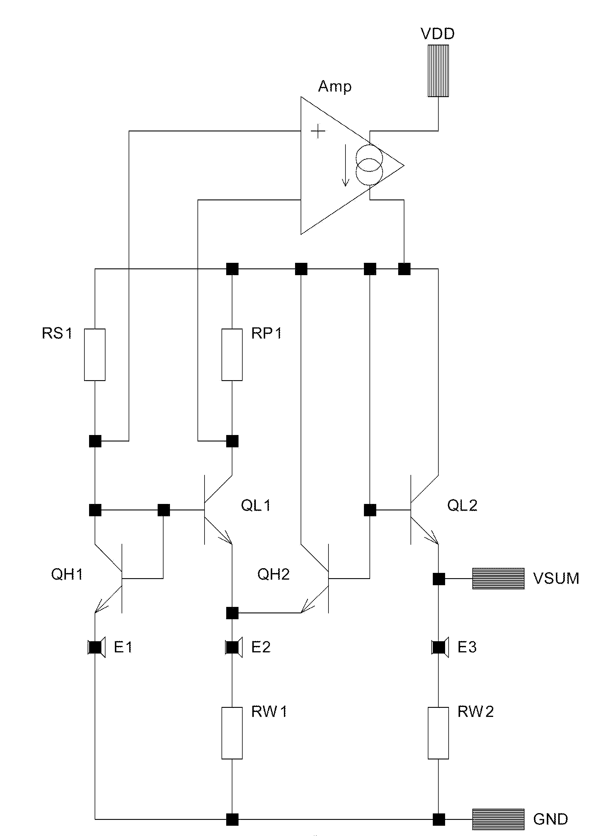
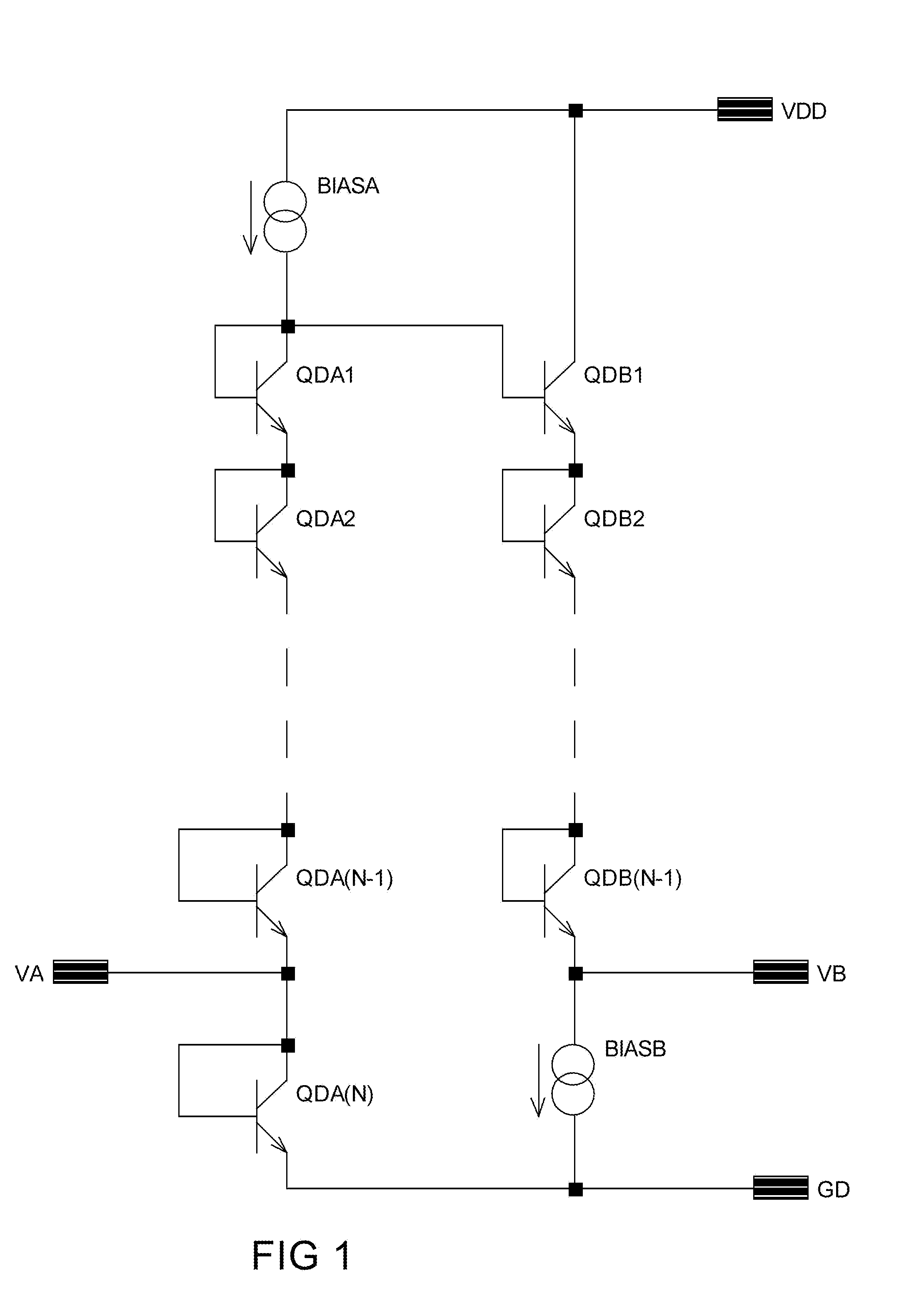
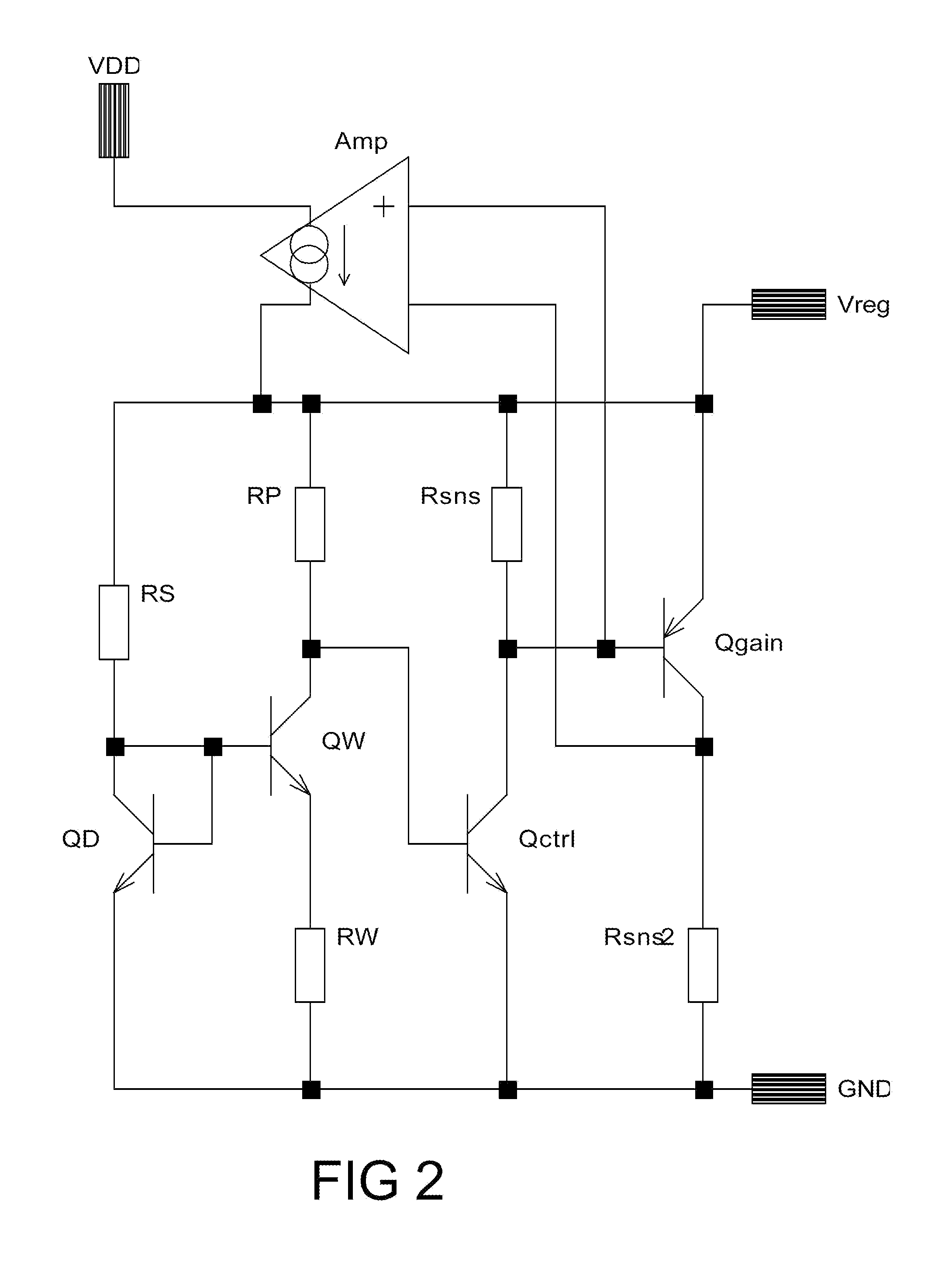
[0025]All the circuit diagrams in the drawings use conventional notation for components such as transistors, resistors and current supplies and the manner in which the various individual components are interconnected will be assumed to be the same as shown in the drawings. In the interest of clarity and conciseness, no verbal description of the interconnections will be repeated in the text below.

[0026]FIG. 1 shows the earliest bandgap arrangement due to Hilbiber. Using compact modern IC Transistors would allow an Area Ratio of at least 1:100 for the QDA Transistors relative to the QDB transistors, and this would require N=5, i.e. a total of 9 Transistors in order for the output to be at the bandgap potential. The minimum supply would therefore be about 4.5 Volts—considerably lower than would have been practical when Hilbiber designed the original reference. The noise levels may be reduced by using fewer stages. It may even be practical to increase the Area Ratio to 1:220, which woul...


PUM


Abstract

A circuit for use in a current source or a proportional to absolute temperature sensor or in a bandgap regulator, the circuit comprising at least two PTAT cells the operating Voltages of whose components overlap, the PTAT contribution to the output including the sum of the outputs of the two PTAT cells.

Description

FIELD OF THE INVENTION[0001]The present invention relates to a temperature sensor, in particular to a temperature sensor that develops a Voltage that is proportional to absolute temperature. The invention equally relates to the provision of a bandgap voltage reference circuit.BACKGROUND OF THE INVENTION[0002]The earliest known bandgap regulator was designed by Hilbiber in about 1964, and described in U.S. Pat. No. 3,271,660. This consisted of two stacks of transistors, each arranged to provide a diode-equivalent Voltage level shift (herein referred to as “Diodes”) as shown in the appended FIG. 1. The first stack comprised a number of Diodes QDA1 . . . QDA(N) connected in series and forward biased, and the other comprised one fewer Diodes QDB1 . . . QDB(N−1) connected in series and forward biased; the positive ends of each series-connected group were joined. The difference in the effective current densities in the Diodes QDB(1) . . . QDB(N−1) in the second group and the corresponding...

Claims


Application Information

Patent Timeline
Patent Type & Authority Applications(United States)
IPC IPC(8): G05F3/30
CPCG05F3/30G01K7/01G05F3/225G05F3/245
Inventor ROKOS, GEORGE HEDLEY STORM
Owner ADAPTALOG
Why Eureka
Try Eureka