Image displaying apparatus, and a method for adjusting vibrating condition of a reflection mirror in the image displaying apparatus

a technology of image displaying apparatus and reflection mirror, which is applied in the direction of instruments, static indicating devices, optical elements, etc., can solve the problems of generating various ill effects on the structure of the mems resonance mirror, affecting the and affecting the swinging condition of the mems, so as to prevent ill effects and prevent ill influences from being extorted. , the effect of high brightness of the projection imag

Active Publication Date: 2009-03-05
MAXELL HLDG LTD
View PDF4 Cites 61 Cited by
  • Summary
  • Abstract
  • Description
  • Claims
  • Application Information

AI Technical Summary

Benefits of technology

[0007]By the way, with the image displaying apparatus comprising therein the MEMS resonance mirrors, being pivotally supported so as to swing, freely, into the vertical direction and the horizontal direction, it is possible to achieve an increase of color reproduction region and / or a high brightness, with a relatively low cost and with ease, in particular, upon the image formed on the screen, by projecting the laser beam lights emitted from the light source and reflected upon the MEMS resonance mirrors. This is due to the fact that, accompanying an advancement of the semiconductor laser technology in recent years, it is possible to achieve an increase of output energy from the laser light source and / or an increase of an efficiency in electric / photo conversion, and that it is also possible to achieve an increase in selectivity of oscillation wavelengths within the visible lights.
[0009]Accordingly, an object of the present invention is to provide an image displaying apparatus, comprising there in reflection mirrors, which can vibrate in one (1) axial direction or two (2) axial directions, wherein the structures of reflection mirrors thereof can be protected from being affected with ill influences applied thereupon, even if increasing the output energy from the light source for achieving the high brightness of the projection image.
[0021]According to the present invention, within the image displaying apparatus comprising the reflection mirror vibrating in a first axial direction and a second axial direction, even when increasing an output energy from the light source, so as to obtain high brightness of the projection image, it is possible to prevent ill effects from being generated in the structures of the reflection mirror due to that, and therefore it is possible to prevent ill influences from being extorted upon the driving condition of the reflection mirror.

Problems solved by technology

For this reason, if increasing the output energy from the laser light source, in order to achieve the high brightness of an image or picture projected on the screen, then an amount of heats on the MEMS resonance mirrors is increased, thereby rising up temperature of the MEMS resonance mirrors; i.e., due to this, there is a possibility of generating various ill effects on the structures of the MEMS resonance mirrors.
In addition to that mentioned above, there is also a possibility of bringing about an ill influence upon swinging condition of the MEMS resonance mirrors, which are pivotally supported so as to swing, freely, into the vertical direction and the horizontal direction.
Therefore, with the conventional image displaying apparatus, actually, it is impossible to achieve the high brightness of the projection image formed on the screen, by increasing the output energy from the laser light source.

Method used


Image

  • Image displaying apparatus, and a method for adjusting vibrating condition of a reflection mirror in the image displaying apparatus
  • Image displaying apparatus, and a method for adjusting vibrating condition of a reflection mirror in the image displaying apparatus
  • Image displaying apparatus, and a method for adjusting vibrating condition of a reflection mirror in the image displaying apparatus

Examples


first embodiment

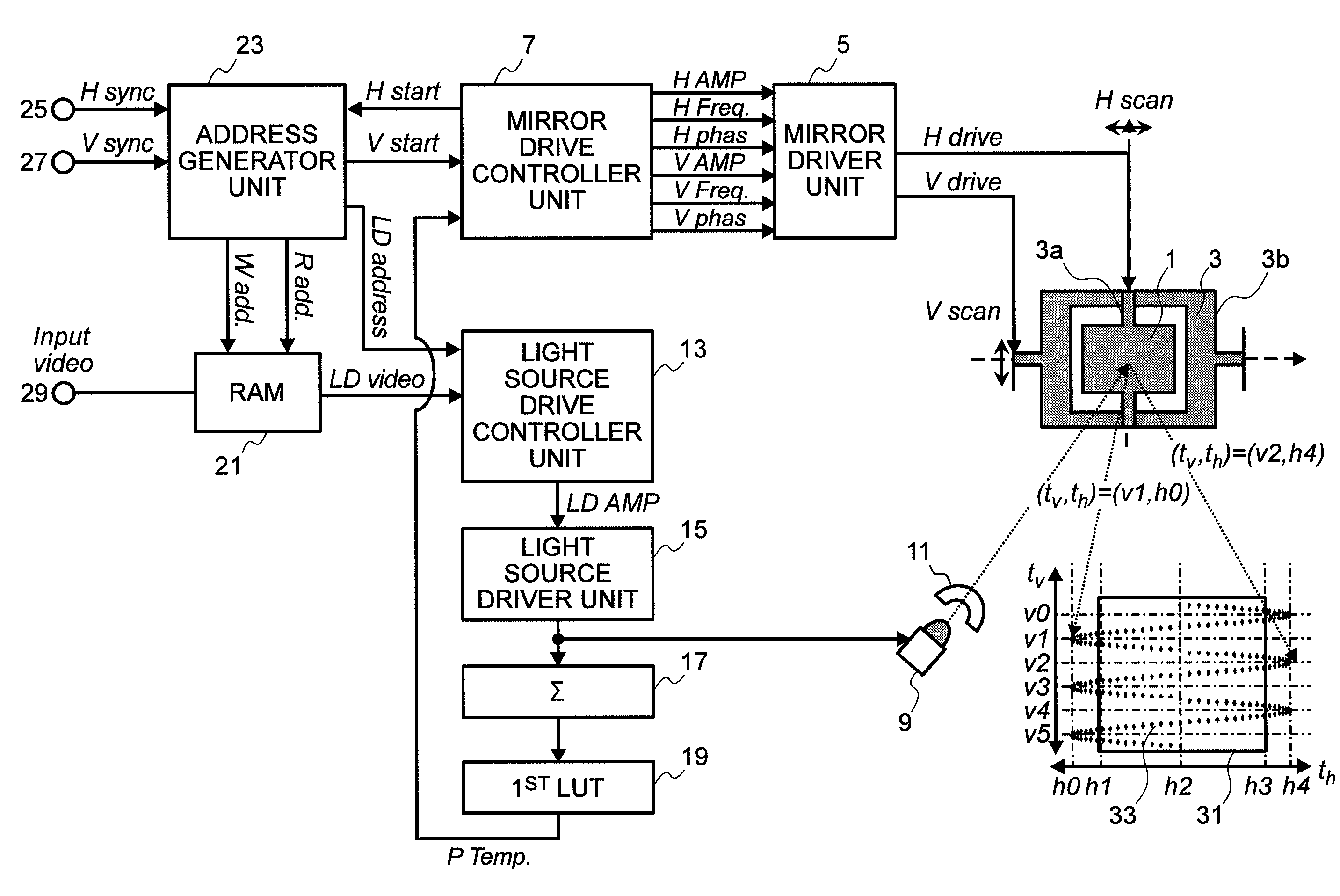
[0033]FIG. 1 is a function block diagram for showing the entire structures of an image displaying apparatus, according to the present invention.

[0034]The image displaying apparatus mentioned above comprises, as shown in FIG. 1, a MEMS resonance mirror (hereinafter, being described as “micro mirror”) 1, a mirror driving / holding mechanism 3, a mirror driver portion or unit 5, a mirror drive controller portion or unit 7, a light source 9, and a beam light producer lens 11. In addition to those mentioned above, the image displaying apparatus mentioned above further also comprises a light source drive controller portion or unit 13, a light source driver portion or unit 15, a light amount integrator portion or unit 17, a first lookup table holder portion or unit (hereinafter, being described as “first LU holder unit”) 19, a RAM 21 and an address generator portion or unit 23.

[0035]The address generator unit 23 generates a write-in address signal (hereinafter, being described as “W add”) to...

second embodiment

[0072]FIG. 3 is a function block diagram for showing the entire structures of the image displaying apparatus, according to the present invention.

[0073]The image displaying apparatus shown in FIG. 3 differs from the image displaying apparatus (e.g., according to the first embodiment of the present invention) shown in FIG. 1, in the structures thereof, in particular, in the following aspects: i.e., removing the light amount integrator unit 17 and the first LUT holder unit 19 from the structures shown in FIG. 1, and also adding a temperature detector unit 35, a detected temperature value integrator unit 37, and a second lookup table holder unit (hereinafter, being described as “second LUT holder unit”) 39. However, with the structures shown in FIG. 3, but other than those are same to those shown in FIG. 1, and therefore will be omitted the explanation about the details thereof.

[0074]In FIG. 3, the temperature detector unit 35 is disposed in vicinity of the micro mirror 1, and it detect...

third embodiment

[0079]FIG. 4 is a function block diagram for showing the entire structures of the image displaying apparatus, according to the present invention.

[0080]The image displaying apparatus shown in FIG. 4 differs from the image displaying apparatus (e.g., according to the first embodiment of the present invention) shown in FIG. 1, in particular, by newly adding a photo receiving member 41, a photo / eclectic converter element 43 and a condition detector portion 45, in the structures thereof. However, since the structures shown in FIG. 4, but other than those mentioned above, are same to those shown in FIG. 1, and therefore in this FIG. 4, the same reference numerals are attached for those shown in FIG. 1, but the explanation will be omitted about the details thereof.

[0081]In FIG. 4, the photo receiving member 41 is a line-like member. This photo receiving member 41 is disposed along the axis tv in FIG. 4, at a position at one of the ends of the vibration (or oscillation) in the horizontal (H...


PUM


Abstract

For enabling to prevent ill effects from being generated in the structures of a reflection mirror, even if increasing an output energy from a light source, thereby preventing ill influences from being exerted on the driving condition thereof, a mirror drive controller unit 7 reads out history data of the past, relating to temperature changes on a micro mirror 1, from a first LUT holder unit 19. Upon basis of the read-out history data of the past is presumed the temperature on the micro mirror 1 at the present time. The presumed temperature on the micro mirror 1 is temperature P temp of the micro mirror 1 at the present time, and upon that P temp are changed vibration (or oscillation) condition of the micro mirror 1 in the horizontal (H) direction and vibration (or oscillation) condition thereof in the vertical (V) direction.

Description

BACKGROUND OF THE INVENTION[0001]1. Field of the Invention[0002]The present invention relates to an image displaying apparatus, comprising therein a reflection mirror for displaying an object to be projected by receiving and reflecting a light irradiated from a light source into a predetermined direction, and a method for adjusting vibrating condition of the reflection mirror in the image displaying apparatus.[0003]2. Related Art[0004]In recent years are tried applications of technologies, such as, MEMS (Micro Electro Mechanical System) and a semiconductor laser technology, into household electric appliances. As an example of that can be listed up an application into an image displaying apparatus, for drawing an image thereon, with using a laser light made of wavelength components of visible lights, as a light source thereof (for example, see the following Non-Patent Document 1). Also, within an image displaying apparatus, comprising therein MEMS resonance mirrors is made a proposal...

Claims


Application Information

Patent Timeline
Patent Type & Authority Applications(United States)
IPC IPC(8): G03B21/16
CPCG03B21/00G03B21/28G03B33/06H04N9/3129H04N9/3155G09G2360/145G09G3/025G09G2320/0233G09G2320/0285G09G2320/041H04N9/3164G03B21/008
Inventor KOBORI, TOMOKIOUCHI, SATOSHIHIRATA, KOJIIKEDA, HIDEHIROMURATA, SEIJISHIKITA, KAZUO
Owner MAXELL HLDG LTD
Why Eureka
Try Eureka