Apparatus for cooling of electrical elements

a technology for electrical elements and cooling devices, applied in lighting and heating devices, cell components, cell component details, etc., can solve the problems of unnecessary physical space and considerable effort of cooling devices, and achieve the effects of simple production, good cooling performance and occupying little physical spa

Active Publication Date: 2009-03-05
BEHR GMBH & CO KG
View PDF12 Cites 32 Cited by
  • Summary
  • Abstract
  • Description
  • Claims
  • Application Information

AI Technical Summary

Benefits of technology

[0004]The object of the invention is to specify an apparatus for cooling of electrical elements, w

Problems solved by technology

An apparatus such as this involves considerable effort during production, with large intermediate spaces remaining betwee

Method used


Image

  • Apparatus for cooling of electrical elements
  • Apparatus for cooling of electrical elements
  • Apparatus for cooling of electrical elements

Examples


Embodiment Construction

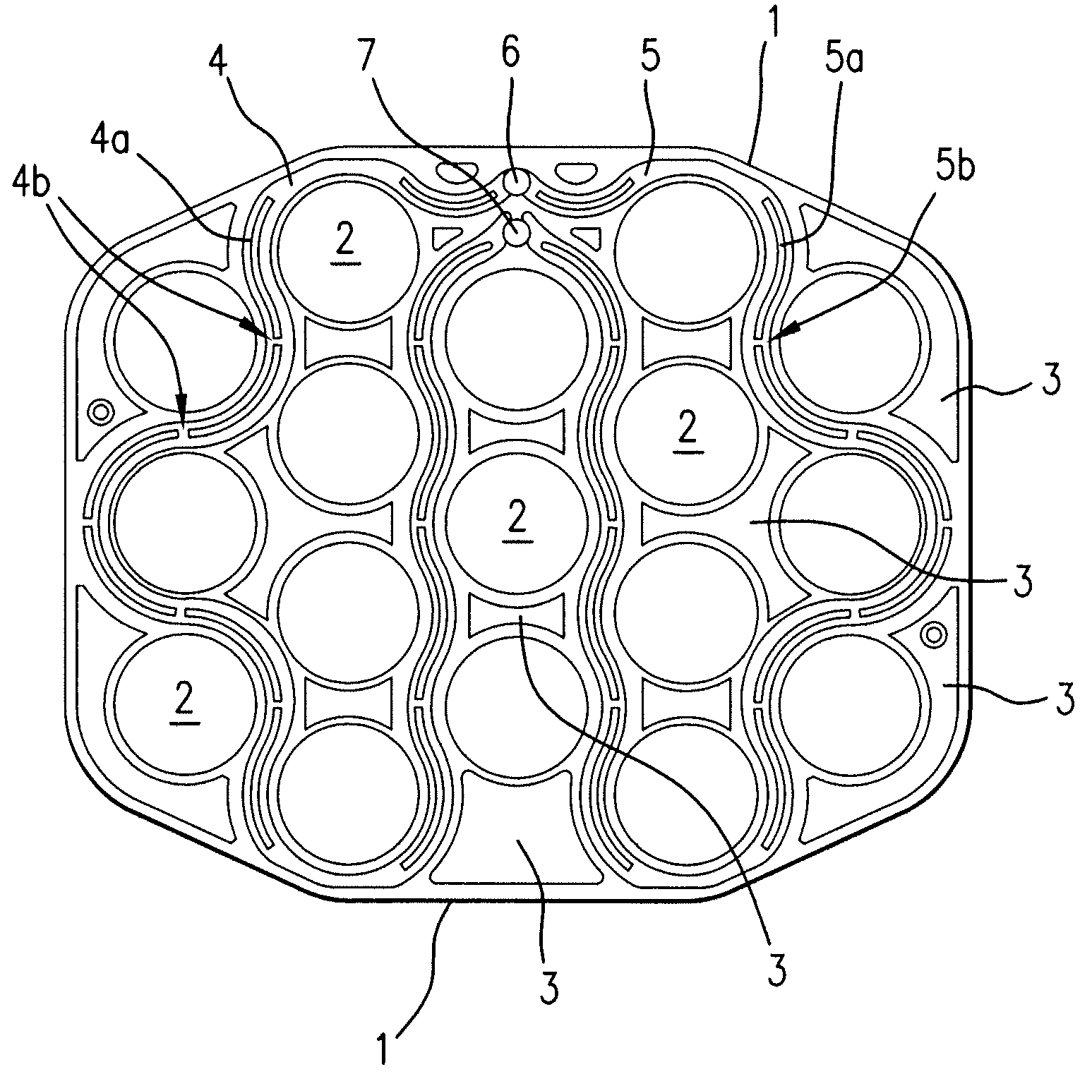
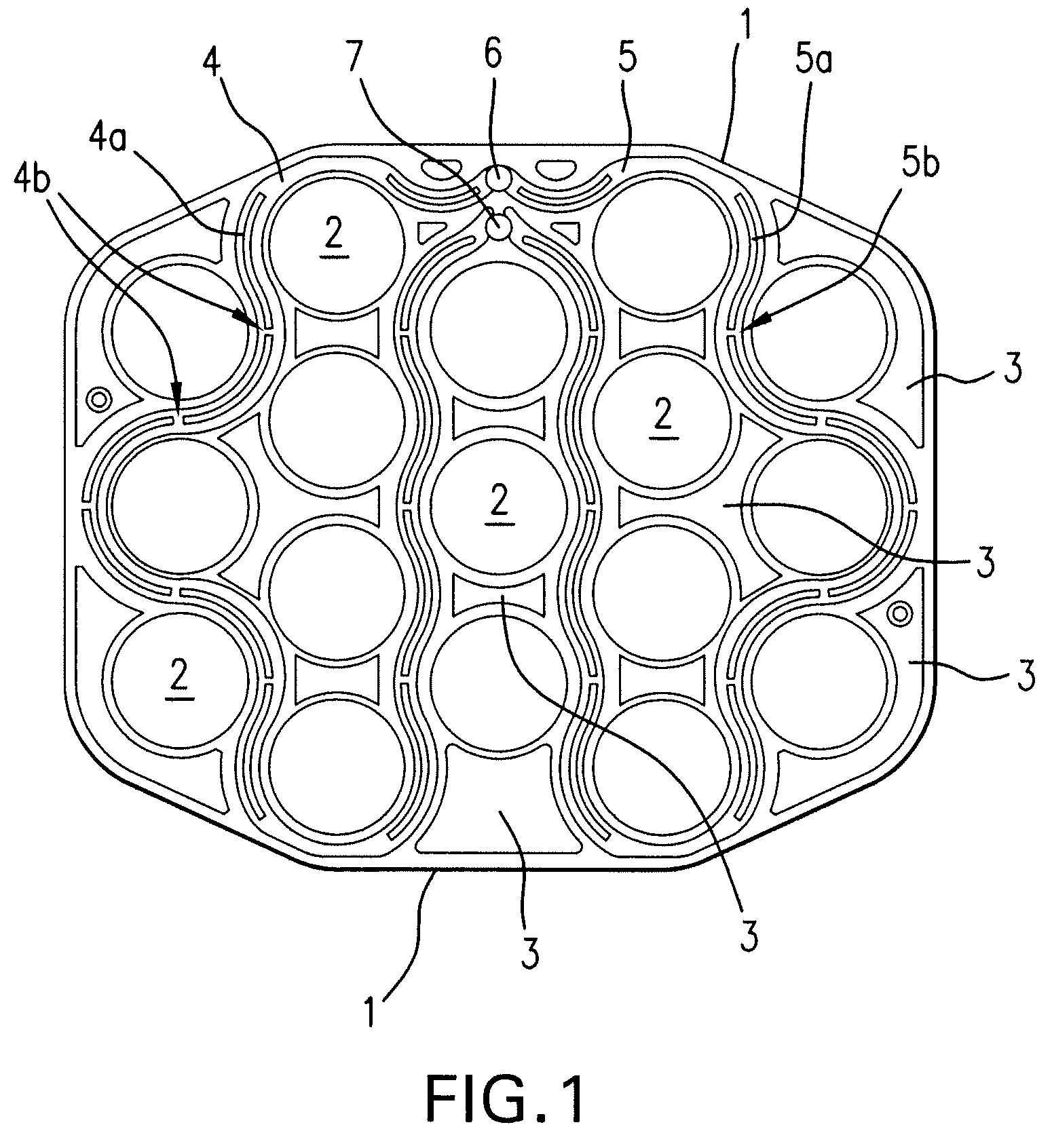
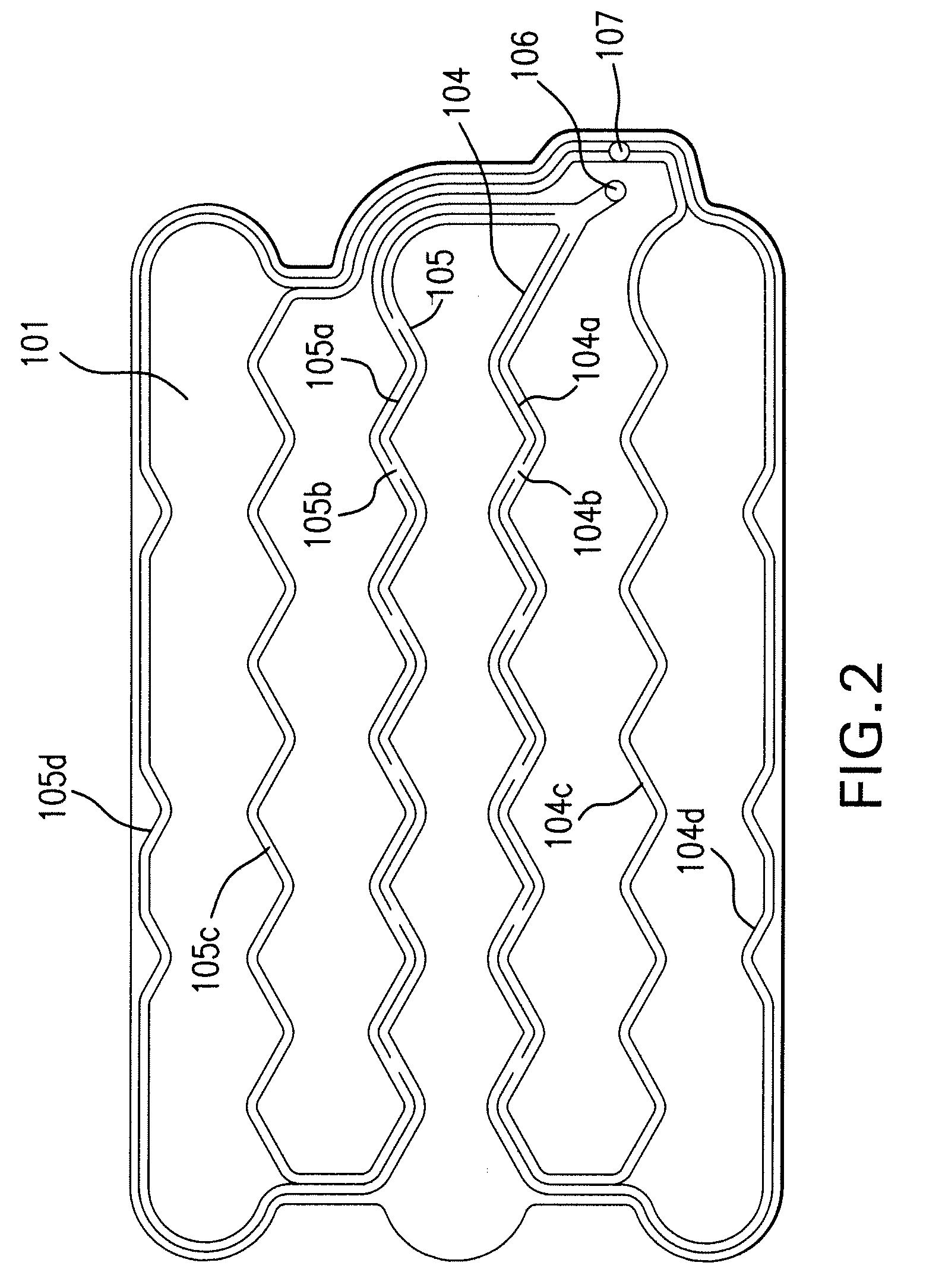
[0009]In one preferred development, thermal guide bodies are arranged on the heat sink and are adjacent to the electrical elements, with the guide bodies extending essentially at right angles to the heat sink and making thermal contact with the electrical elements. This makes use of intermediate spaces which remain between the elements, in order to reduce the thermal resistance. In the interest of simple production and good thermal connection between the guide bodies and the heat sink, the guide bodies are in this case integrally connected to the heat sink, in particular by soldering. In a further preferred embodiment, at least some of the guide bodies are in the form of cups with an at least partially circumferential wall, with one electrical element in each case being held in one of the cup-shaped guide bodies. This allows an expedient combination of thermal heat dissipation with retention of the elements. Alternatively or additionally, at least some of the guide bodies are each i...


PUM


Abstract

Apparatus for cooling electrical elements, comprising a heat sink (1, 101, 201) through which a coolant can flow, a plurality of electrical elements (2, 102, 202) which each have a bottom surface and a side surface, with the bottom surfaces being aligned essentially on one plane, with the heat sink (1, 101, 201) having at least one channel (4, 5, 104, 105, 204, 205) through which a coolant can flow and making thermal contact with the electrical elements (2, 102, 202), characterized in that the heat sink (1, 101, 202) extends essentially parallel to the plane of the bottom surfaces, with the channel (4, 5, 104, 105, 204, 205) in the heat sink having a profile which is matched to edges of the electrical elements (2, 102, 202).

Description

CROSS-REFERENCE TO RELATED PATENT APPLICATIONS[0001]Germany Priority Application 10 2006 045 564.9, filed Sep. 25, 2006 including the specification, drawings, claims and abstract, is incorporated herein by reference in its entirety. European Patent Office Priority Application 07017195.4, filed Sep. 3, 2007 including the specification, drawings, claims and abstract, is incorporated herein by reference in its entirety.BACKGROUND OF THE INVENTION[0002]The invention relates to an apparatus for cooling of electrical elements, according to the precharacterizing clause of Claim 1, and to a method for producing the apparatus, according to the features of Claim 36.[0003]EP 0 177 225 A1 describes an active cooling system for electrochemical cells, in which cylindrical rechargeable batteries are held between channels, which convey coolant, in thermal contact with the channels, with the channels at least partially surrounding the cylindrical side walls of the electrical rechargeable batteries. ...

Claims


Application Information

Patent Timeline
IPC IPC(8): H05K7/20B60K6/00H01M50/213H01M50/291
CPCB60H1/00278B60H1/00342F28D1/035F28D1/0478F28D2021/0031F28D2021/0094F28F3/046F28F2210/02H01M2/1077H01M10/0525H01M10/5004H01M10/5016H01M10/503H01M10/5059H01M10/5077H01M10/5095H05K7/2029H05K7/20881Y02E60/12B60H2001/00307H01M10/625H01M10/663H01M10/6568H01M10/6557H01M10/643H01M10/613Y02E60/10H01M50/213H01M50/291
Inventor DAMSOHN, HERBERTGNEITING, RONALDISERMEYER, TOBIASLUZ, KLAUSPFENDER, CONRAD
Owner BEHR GMBH & CO KG
Why Eureka
Try Eureka