Sncr distribution grid

a distribution grid and fluidized bed technology, applied in indirect heat exchangers, lighting and heating apparatus, separation processes, etc., can solve problems such as poor mixing of reactant and flue gas

Active Publication Date: 2009-03-05
THE BABCOCK & WILCOX CO
View PDF9 Cites 4 Cited by
  • Summary
  • Abstract
  • Description
  • Claims
  • Application Information

AI Technical Summary

Problems solved by technology

Utilizing nozzles to inject such reactants for SNCR which are installed only on the periphery of walls of the CFB which convey the flue gas flow might not achieve sufficient jet penetration of the reactant into the flue gas flow, resulting in poor mixing of the reactant with the flue gas.

Method used


Image

  • Sncr distribution grid
  • Sncr distribution grid

Examples


Embodiment Construction

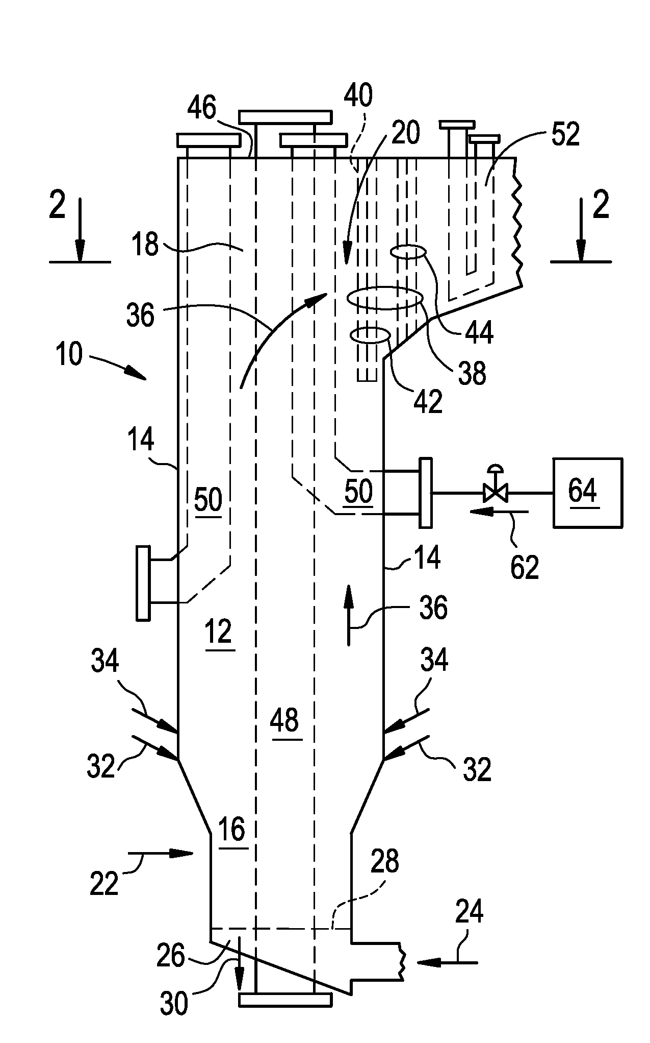
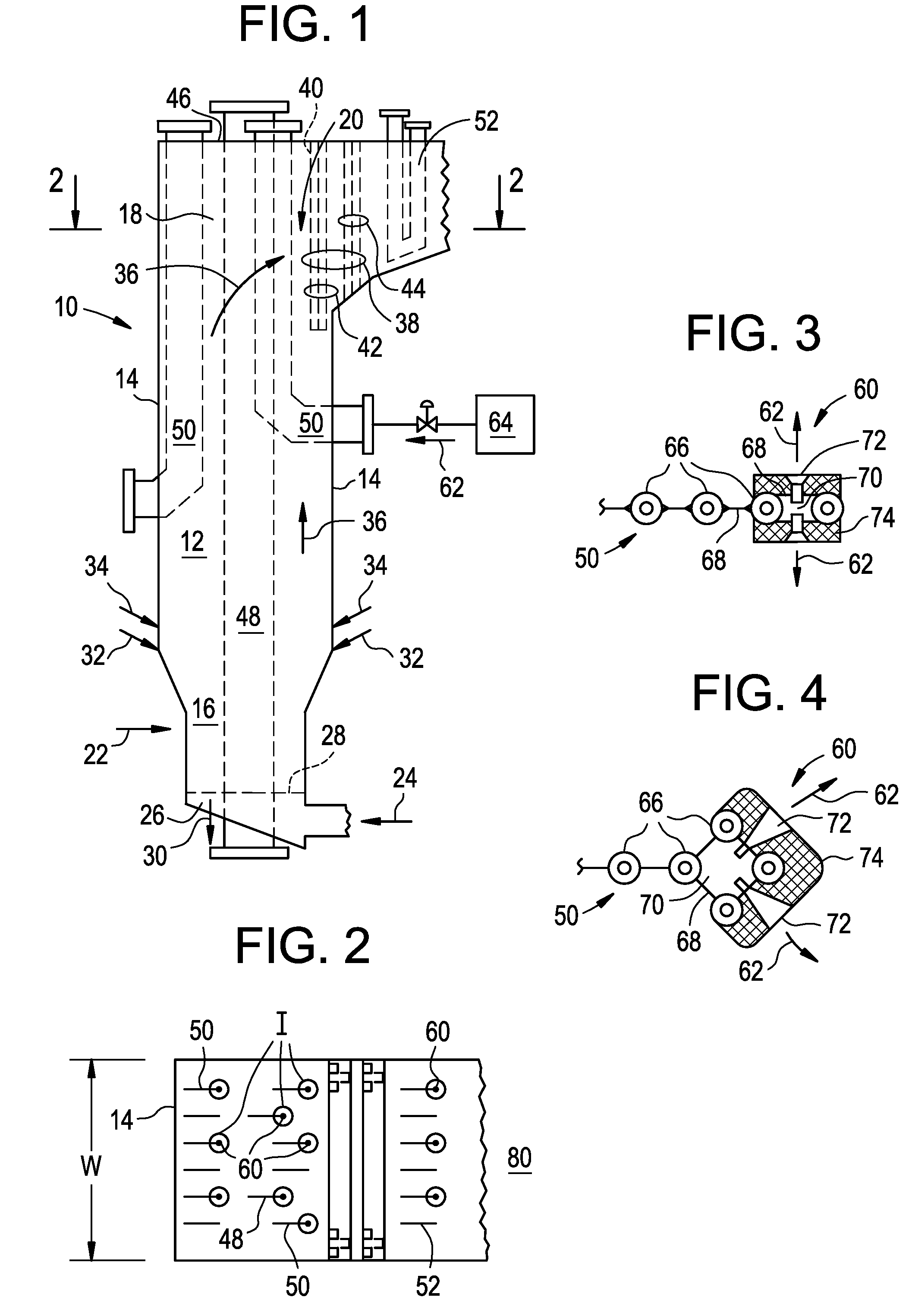
[0013]The present invention overcomes the aforementioned difficulty by providing a particularly designed distribution grid for introducing the reactant into the flue gas flow. The grid comprises one or more elements which are formed by fluid-cooled tubes to which membrane pieces are attached, preferably by welding, to form conduits in between the tubes. The fluid-cooled tubes may be cooled by water and / or steam and the distribution grid is disposed into the flue gas flow. To admit the reactant into the flue gas, nozzles are provided in the membrane and the reactant is conveyed from a location external of the furnace or combustor enclosure, into the conduits so formed, and thence out into the flue gas flow via the nozzles. The spacing between the elements forming the distribution grid, as well as the spacing between the nozzles provided in the membrane is selected to achieve relatively uniform mixing of the dispersed reactant into the flue gas. As described above, the inlet to the co...


PUM

PropertyMeasurementUnit
temperatureaaaaaaaaaa

Abstract

An SNCR distribution grid for introducing a NOx reducing reactant into a flue gas flow. The grid is made of one or more elements which are formed by fluid-cooled tubes to which membrane pieces are attached, preferably by welding, to form conduits in between the tubes. The fluid-cooled tubes may be cooled by water and / or steam and the distribution grid is disposed in the flue gas flow. To admit the reactant into the flue gas, nozzles are provided in the membrane and the reactant is conveyed from a location external of the furnace or combustor enclosure, into the conduits so formed, and thence out into the Flue gas flow via the nozzles.

Description

FIELD OF THE INVENTION[0001]The present invention relates primarily to circulating fluidized bed (CFB) reactors, combustors and / or boilers having impact type particle separators used in the production of steam for industrial applications and / or utility power generation and, more particularly, to an apparatus for introducing ammonia or urea into the flue gas produced by such CFBs which, as part of a selective non-catalytic reduction (SNCR) system, is used to reduce NOx emissions from the CFB. The present invention may also be employed in connection with bubbling fluidized bed reactors, grate-type furnaces, etc.BACKGROUND OF THE INVENTION[0002]The typical operating temperature for the reactors or combustors of such CFBs, and thus the flue gases produced thereby, lies within a temperature range of approximately 1550-1650°F. This temperature range thus lies within an acceptable temperature “window” for the application of selective non-catalytic reduction (SNCR) techniques for reducing N...

Claims


Application Information

Patent Timeline
Patent Type & Authority Applications(United States)
IPC IPC(8): B01J8/44
CPCB01D53/56F28D7/0041B01J4/002B01J8/0045B01J8/0065B01J8/1818B01J8/1827B01J8/1836B01J8/1845B01J8/44B01J19/26B01J2208/00123B01J2208/00132B01J2208/0015B01J2208/00185B01J2208/00194B01J2208/00203B01J2208/00212B01J2208/00504B01J2219/00119B01D53/79
Inventor MARYAMCHIK, MIKHAIL
Owner THE BABCOCK & WILCOX CO
Why Eureka
Try Eureka