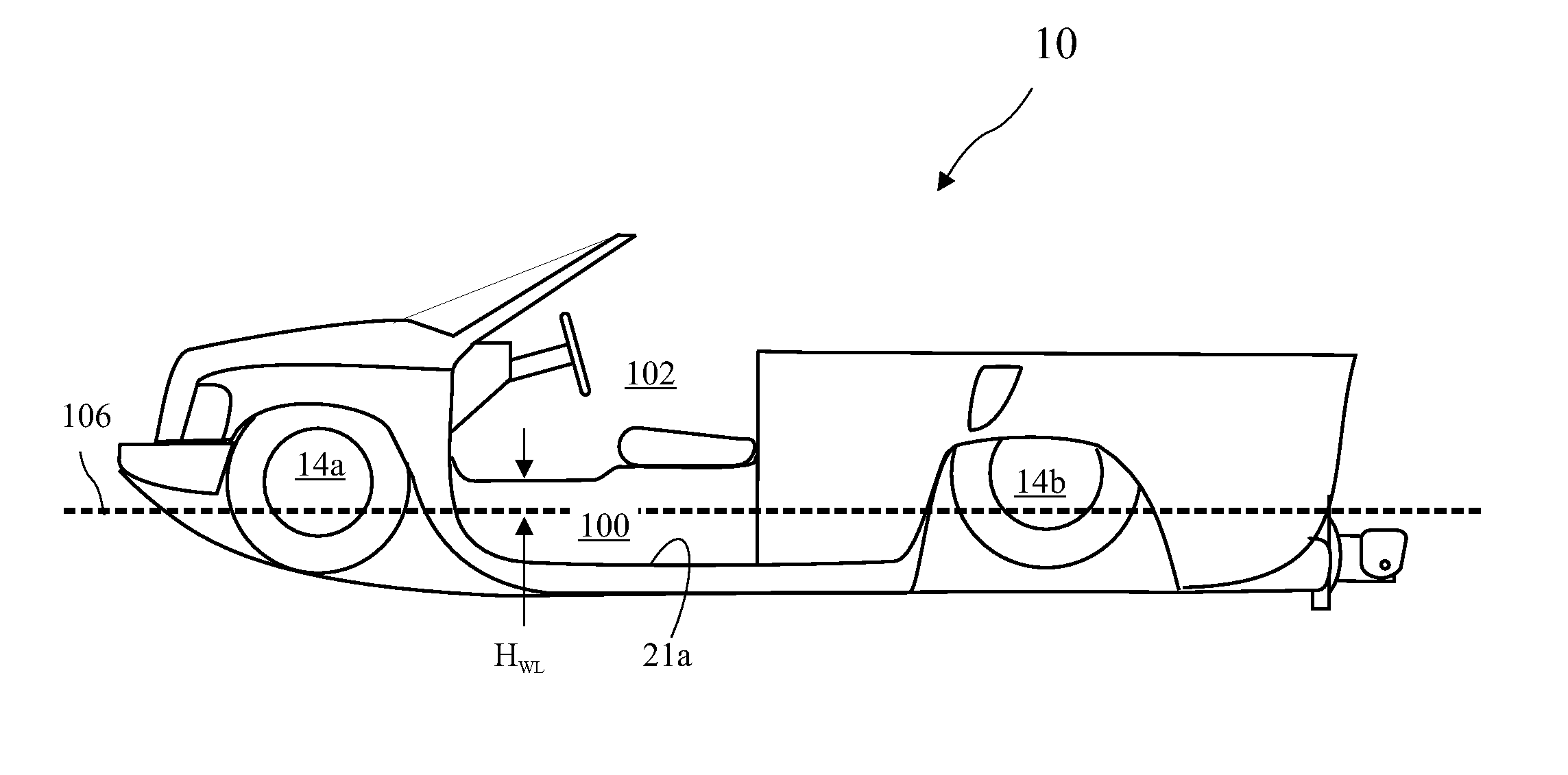
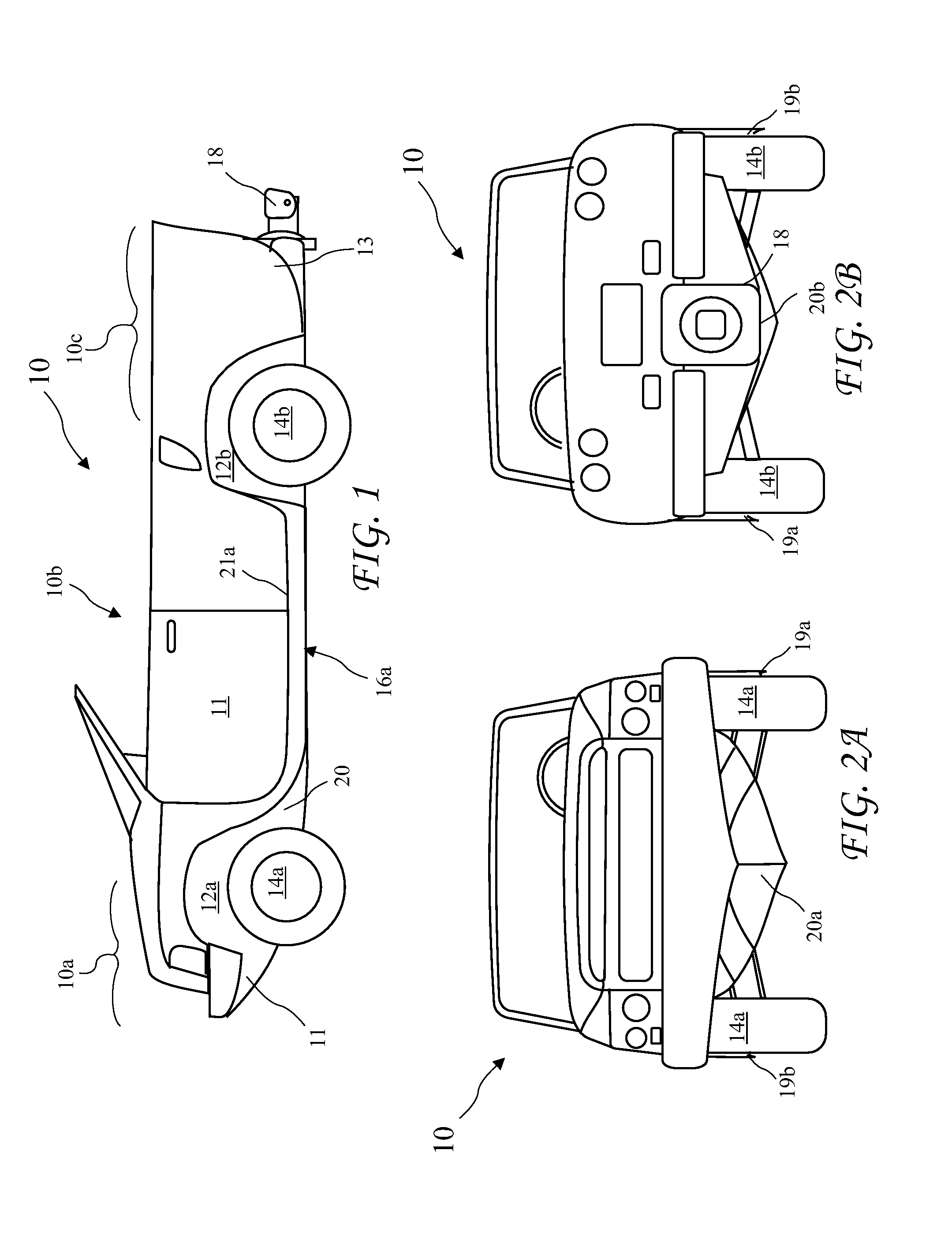
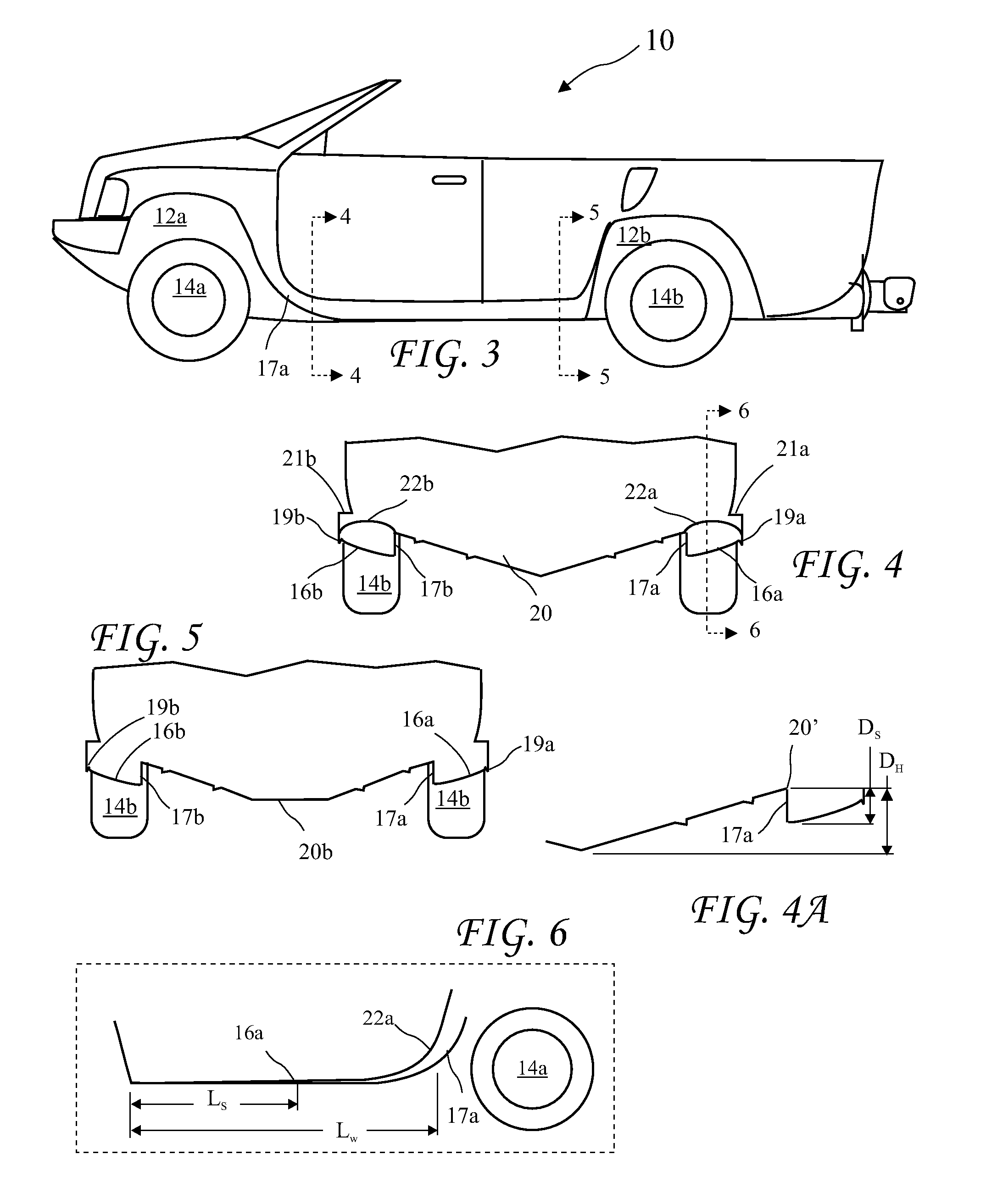
Amphibious vehicle
a technology for amphibious vehicles and propellers, applied in the field of amphibious vehicles, can solve the problems of high cost and difficulty of including a deployable scag, flat bottom boats generally have a poor ride in rough water, and relatively expensive products, etc., to achieve stable ride, improve lift and transition to planing, and maneuverability. high
- Summary
- Abstract
- Description
- Claims
- Application Information
AI Technical Summary
Benefits of technology
Problems solved by technology
Method used
Image
Examples
second embodiment
[0071]the rear suspension 42′ lowered and pushing the rear flaps 52b down is shown in FIG. 12C, and the rear suspension 42′ raised and pulling rear flaps 52b up against the hull according to the present invention is shown in FIG. 12D. The air bags 40 are seen inflated to support the amphibious vehicle 10 during on road operation is seen in FIG. 12C, and the air bags 40′ are shown inflated to lift the suspension 42′ for in-water operation is seen in FIG. 12D.
first embodiment
[0072]a land and water steering unit 60a, according to the present invention, having a Morse cable 74 connected to a rack and pinion unit 64 is shown in FIG. 13A. The connection of the Morse cable to the jet drive 18 through a rod 76 is shown in FIG. 14. A sliding inner cable 70 is connected to steering arms 66 which are connected to the front wheels 14a (see FIG. 1) for on-land steering. The cable 70 is connected to a rod 76 connected to the nozzle of the jet drive 18 to steer in-water. The rack and pinion unit 60 may be a power rack and pinion steering unit or a manual rack and pinion steering unit. Such a direct cable connection between the steering arms 66 and the jet drive 18 provides a similar feel to on-land and in-water steering thus making the transition between in-water and on-land more natural.
[0073]A perspective view of a second embodiment of a land and water steering unit 60b, according to the present invention, with the Morse cable 74 connected to the rack and pinion s...
third embodiment
[0081]While the spring and sliding members of a land and water steering unit 60c are described above at the rack and pinion steering unit end of the Morse cable 74, a similar apparatus may reside at the jet drive 18 to provide the same result.
[0082]A significant advantage of the second embodiment of a land and water steering unit 60b is that in the centered position, the slot 82 and the spring 84 are perpendicular to the rod 88. While the third embodiment of a land and water steering unit 60c provides a somewhat more simple and intuitive design, the springs 92a and 92b, and the sliding direction of the sliding of the second sliding member 93 are aligned with the rod 88. As a result, the second sliding member 93 may not hold the jet drive 18 in a centered position at high speed straight running when water impacts the sides of the jet drive 18, i.e., water forces on the jet drive 18 may be sufficient to compress the springs 92a and / or 92b and somewhat turn the jet drive 18. Because ne...
PUM
 Abstract
Description
Claims
Application Information
 - R&D
- Intellectual Property
- Life Sciences
- Materials
- Tech Scout
- Unparalleled Data Quality
- Higher Quality Content
- 60% Fewer Hallucinations
Browse by: Latest US Patents, China's latest patents, Technical Efficacy Thesaurus, Application Domain, Technology Topic, Popular Technical Reports.
© 2025 PatSnap. All rights reserved.Legal|Privacy policy|Modern Slavery Act Transparency Statement|Sitemap|About US| Contact US: help@patsnap.com


