Flush Mount Panels With Interconnects

a technology of interconnection and flush mount, which is applied in the direction of transducer casings/cabinets/supports, loudspeakers, electrical transducers, etc., can solve the problems of ineffective attaching components in other positions than along the ceiling joist, difficult to line up or evenly space multiple components, and large amount of work in taking measurements and making minor adjustments, etc. , to prevent cracking and fraying, cost-effective fabrication of devices, and small tolerances

Inactive Publication Date: 2009-03-12
DANA INNOVATIONS
View PDF10 Cites 17 Cited by
  • Summary
  • Abstract
  • Description
  • Claims
  • Application Information

AI Technical Summary

Benefits of technology

[0010]Each panel preferably has at least one receiver that can be factory fabricated into one contiguous assembly. Such receivers can advantageously be made of a strong and durable thermoset bracket, or other material that is more suited to hold a mounted device than the gypsum typically used in wallboards. Providing a pre-fabricated panel designed to accept specific components greatly facilitates installation by eliminating the need for on-site precision measurements.

Problems solved by technology

However, since the cutouts are performed at the job site, it can be difficult to line up or evenly space multiple components.
Even where the task can be performed, there is a considerable amount of work exerted in taking measurements and making minor adjustments.
Weber, however, is ineffective at attaching components in positions other than along a ceiling joist, and Eichner cannot be used for recessed components integrated with the existing wall or ceiling.
Attaching the components directly to the support beam means that the centerlines of the components are out of alignment with one another.
However, adding additional support beams for each mounted component is time consuming, labor intensive, and is still prone to errors if the installer makes a measurement mistake.
However, building an entire wall in advance at an off-site location is very often impractical, especially when making a late installation decision after a wall has been installed.
Additionally, none of the prior art teaches arranging mounted components that achieve a flush-mount appearance in walls, ceilings, and other structures, in which little or even no finishing is required around the periphery of the opening.

Method used


Image

  • Flush Mount Panels With Interconnects
  • Flush Mount Panels With Interconnects
  • Flush Mount Panels With Interconnects

Examples


Embodiment Construction

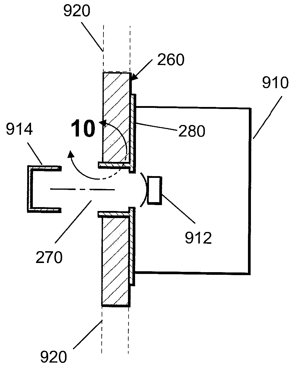
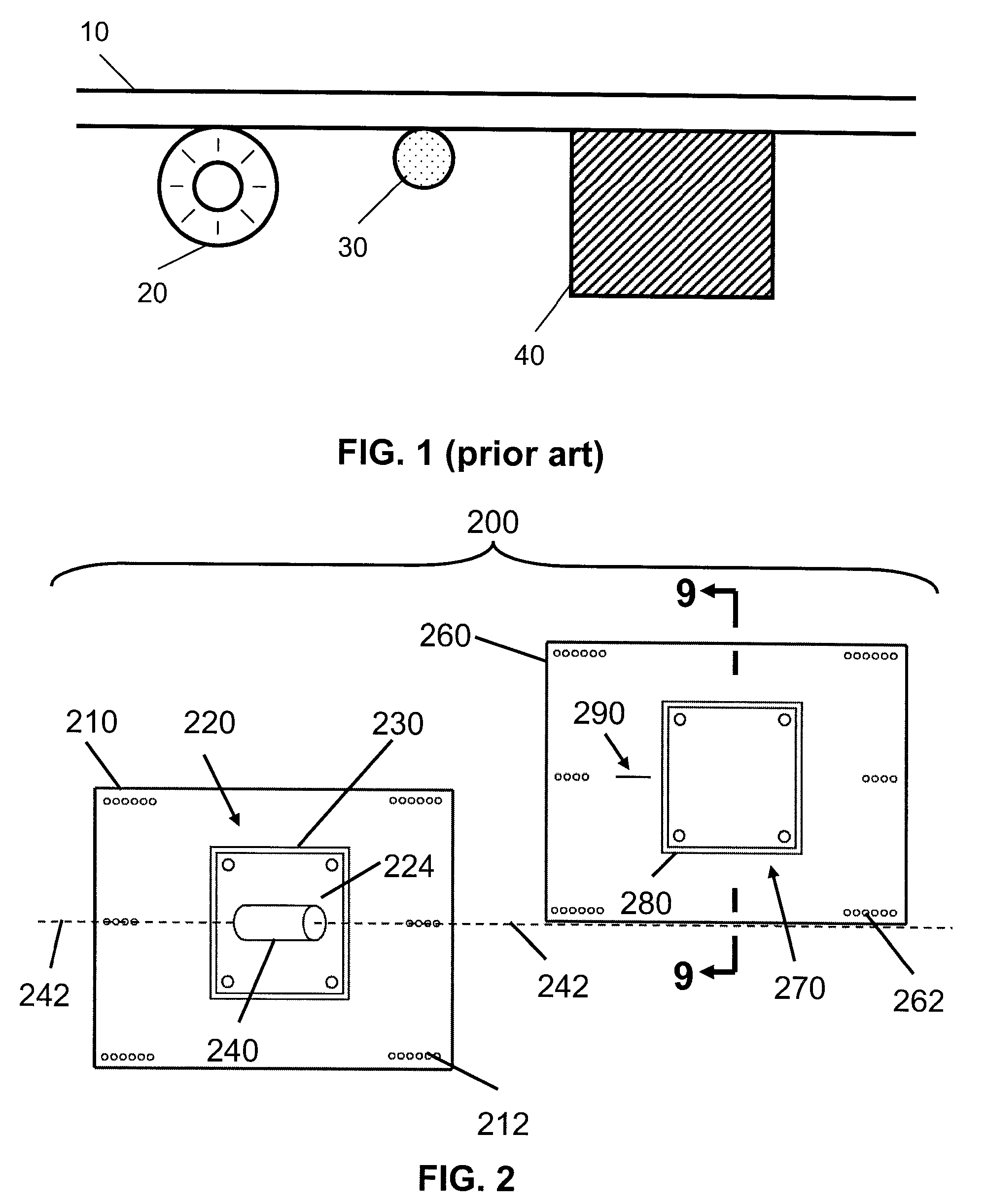
[0051]In FIG. 2 a component mounting apparatus 200 generally includes a panel 210, with opening 220 and panel 260 with opening 270. It should be appreciated that while each bracket is sized and dimensioned to hold a specific component, the brackets could be identical to one another to create a “universal bracketing system” that can hold components of various sizes.

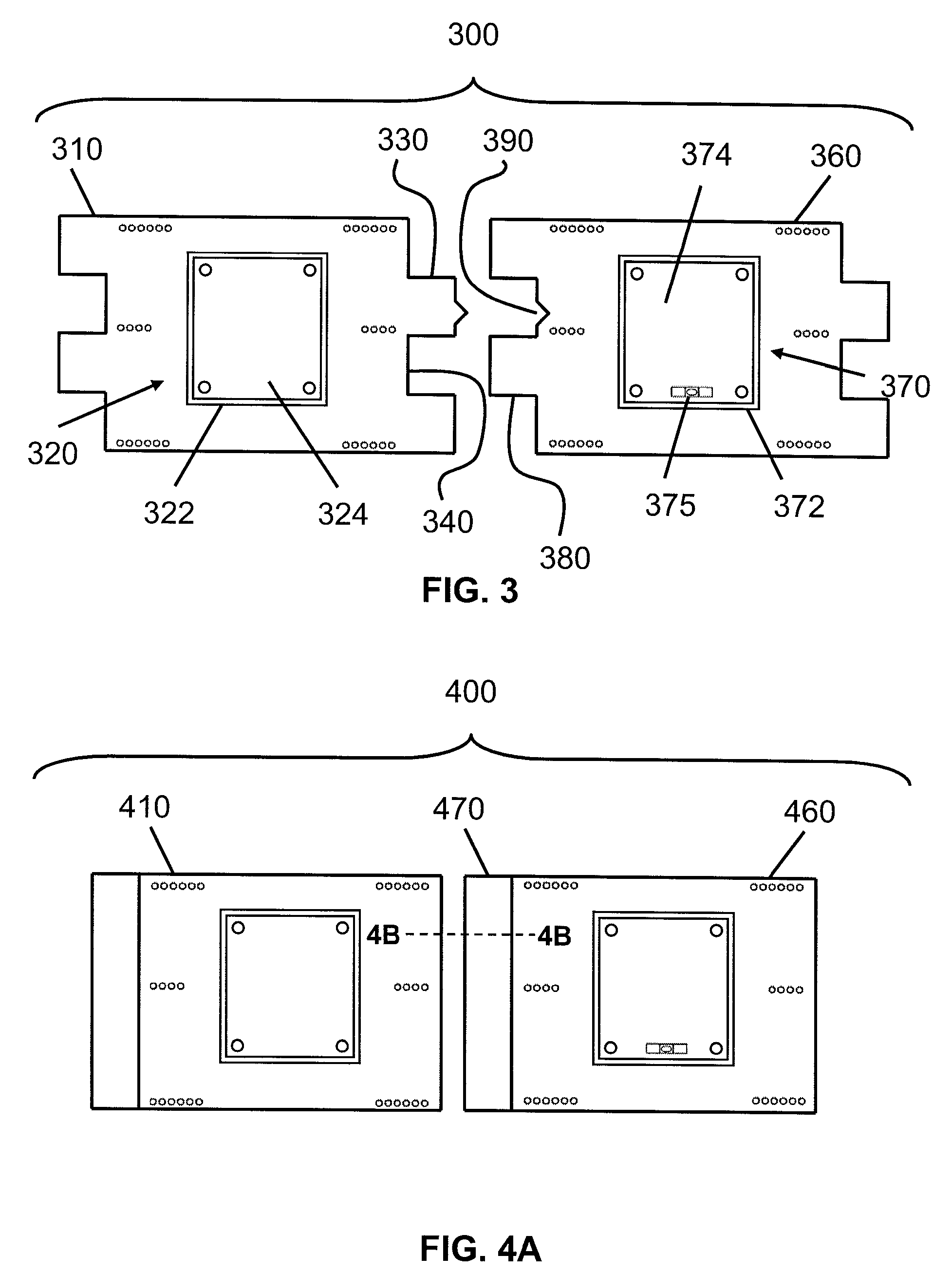
[0052]Panel 210 and panel 260 are preferably substantially identical to one another in terms of shape, size, dimensions, and material, but can vary from one another without departing from the scope of the previous invention. Where the specification refers to only one panel in a figure, it is to be assumed that the other panel in the figure has the same features, unless otherwise stated.

[0053]Panel 210 is a piece of gypsum board, wood, plastic, or other material (or combination of materials) sufficiently strong to support a speaker or other desired component between two studs of a wall, or joists in a ceiling, or other supp...


PUM


Abstract

The present invention provides a system and method of aligning wall or ceiling mounted components. The mounted components are placed within brackets which, in turn, are placed within panels that are embedded into the wall or ceiling. The panels are pre-designed to be installed in precise alignment with respect to one another using various alignment tools or interlocking methods. Once the panels and components are installed into the wall or ceiling, the components are automatically aligned with respect to one another.

Description

[0001]This application is a continuation-in-part of Ser. No. 11 / 954,667 filed Dec. 12, 2007, which is a continuation-in-part of Ser. No. 11 / 566,365 filed Dec. 4, 2006, which claims priority to provisional application Ser. No. 60 / 825,162 filed Sep. 11, 2006 and also claims priority to provisional application Ser. No. 60 / 950,237 filed Jul. 17, 2007 and International application ser. no. PCT / US07 / 16404 filed Jul. 19, 2007. All prior applications are incorporated by reference in their entirety.FIELD OF THE INVENTION[0002]The field of the invention is wall and ceiling receptacles.BACKGROUND[0003]Plasma screens, speakers, light switches, electrical outlets, recessed lighting, junction boxes and other components are conventionally mounted by cutting a hole in a wall or ceiling, inserting a bracket, and then installing the component into the bracket. When several components are mounted on the same wall or ceiling, installers typically attempt to line up the components or space out the compo...

Claims


Application Information

Patent Timeline
IPC IPC(8): E04B1/38
CPCE04F13/0883E04F13/0892H02G1/00H02G2200/30H04R1/025H04R2201/021H04R2499/13H02G3/123
Inventor STRUTHERS, SCOTTCALL, RAYSPENCER, GEOFFFETTER, GREG
Owner DANA INNOVATIONS
Why Eureka
Try Eureka