Position detecting device and position detecting method

a position detecting and position detecting technology, applied in the direction of instruments, signalling systems, power supply for data processing, etc., can solve the problems of weak drive signal received from the surrounding coil, large distance between the position indicator and the surrounding coil, etc., to reduce power consumption and prolong the battery life of the mobile terminal

Active Publication Date: 2009-03-12
WACOM CO LTD
View PDF15 Cites 87 Cited by
  • Summary
  • Abstract
  • Description
  • Claims
  • Application Information

AI Technical Summary

Benefits of technology

[0017]Regarding the position detecting devices and the position detecting methods according to various exemplary embodiments of the present invention, since the output level of the drive signal output from the surrounding coil is controlled according to the indicated position of the position indicator, for exa...

Problems solved by technology

With the aforesaid art, however, if the position detecting area of the position detecting device is relatively large, when the position indicator is located near the center of the position detect...

Method used


Image

  • Position detecting device and position detecting method
  • Position detecting device and position detecting method
  • Position detecting device and position detecting method

Examples


Embodiment Construction

)

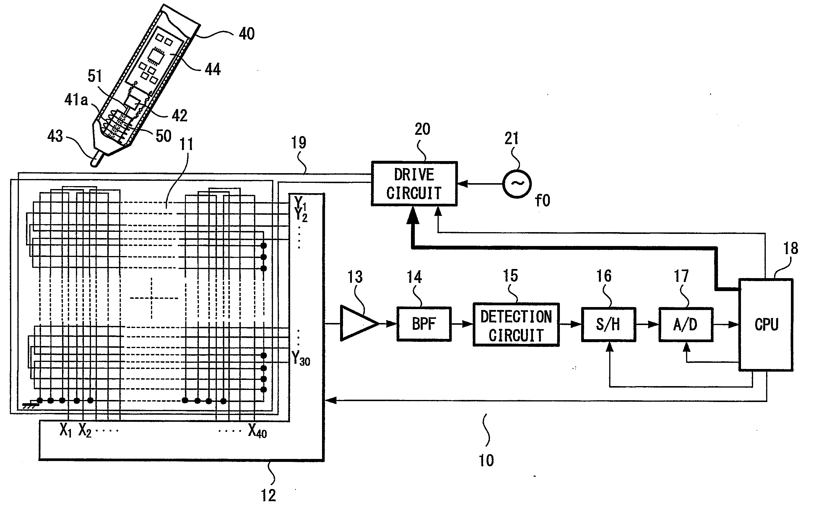
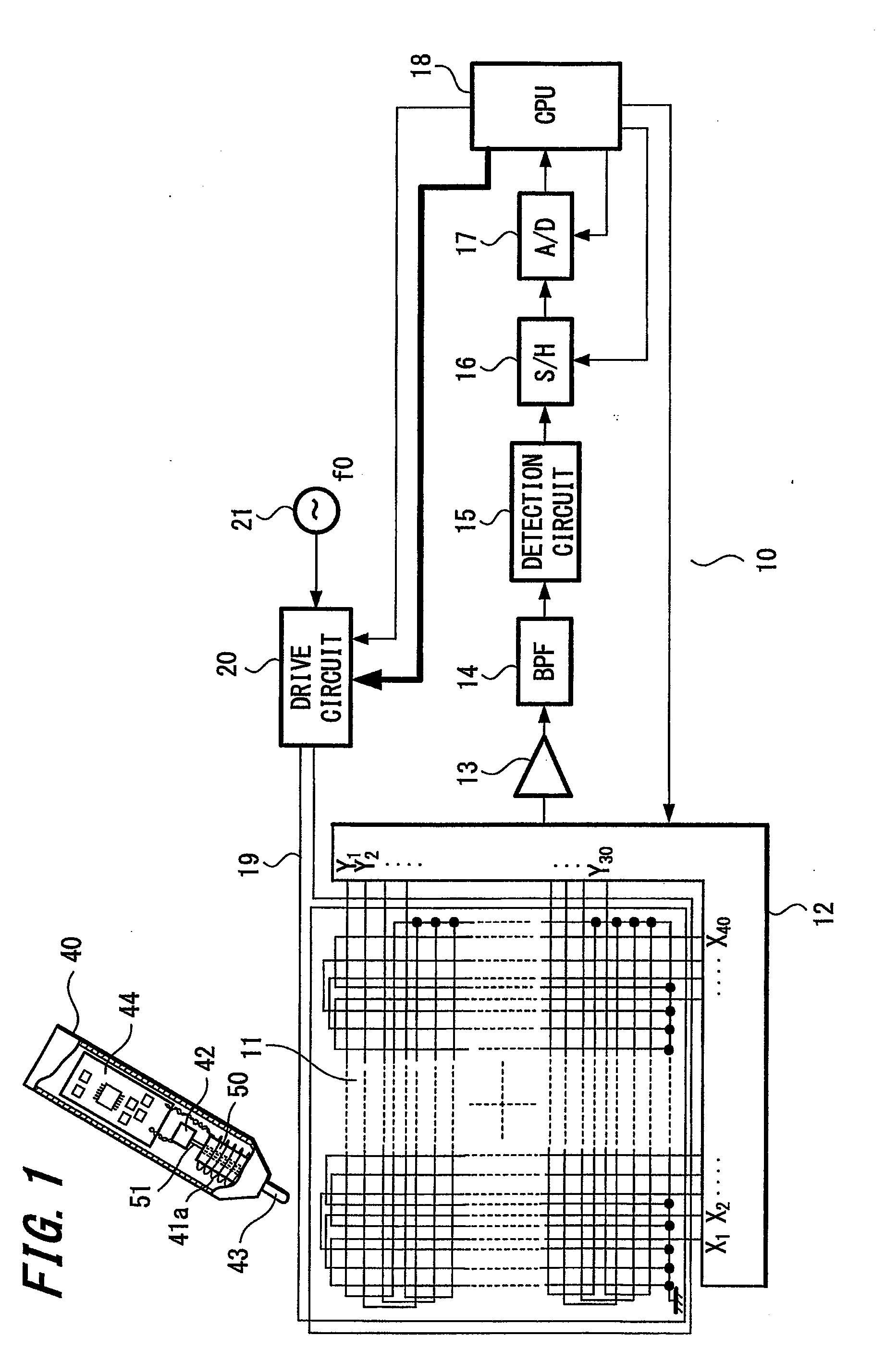
[0025]Embodiments of the present invention will be described below with reference to the attached drawings. FIG. 1 is a diagram showing a configuration of a tablet used as a position detecting device according to one embodiment of the present invention.

[0026]As shown in FIG. 1, a tablet 10 is provided with a sensor including loop coil group 11. The loop coil group 11 has loop coils X1 to X40 and loop coils Y1 to Y30 respectively arranged in an X-axis direction and a Y-axis direction. A position detecting area of the tablet 10 formed by the loop coil group 11 is substantially the same as a display area of a liquid crystal display device (not shown). In other words, the size of the loop coil group 11 and the arrangement pitch of the coils are determined such that the position detecting area substantially corresponds to the display area of the liquid crystal display device.

[0027]Each of the loop coils X1 to X40 and loop coils Y1 to Y30 is connected to a selecting circuit 12 so that a ...


PUM


Abstract

An excitation coil (19) surrounding the periphery of the position detecting area is connected to an oscillating circuit (21), which oscillates at a frequency f0, through a drive circuit (20). A CPU (18) supplies control signals to a selecting circuit (12), a sample-and-hold circuit (16), an A/D conversion circuit (17), and the drive circuit (20). Based on the control signal output from the CPU (18), the drive circuit (20) controls the power of the signal output from the excitation coil (19) to ON or OFF. Further, the strength of the excitation signal supplied from the excitation coil (19) is controlled based on information obtained by analyzing a signal received from a position indicator (40), such as the position indicated by the position indicator on the position detecting area and/or a strength of the signal received from the position indicator.

Description

CROSS-REFERENCES TO RELATED APPLICATIONS[0001]The present application claims priority under 35 U.S.C.§119 from Japanese Patent Application JP 2007-234518 filed in the Japanese Patent Office on Sep. 10, 2007, the entire contents of which being incorporated herein by reference.BACKGROUND OF THE INVENTION[0002]1. Field of the Invention[0003]The present invention relates to a position detecting device, such as a stylus pen, and a position detecting method for detecting a position indicated by such a position indicator.[0004]2. Description of the Related Art[0005]Examples of known position detecting devices are disclosed in Japanese Unexamined Patent Publication No. S63-70326 and Japanese Unexamined Patent Publication No. H07-175572 (corresponding to U.S. Pat. No. 5,679,930, incorporated by reference herein), which have already been put into practical use. With such devices, a position indicated by a position indicator is detected by providing a resonant circuit in the position indicator...

Claims


Application Information

Patent Timeline
IPC IPC(8): G06F3/033G08C21/00G08B5/22G06F3/041
CPCG06F3/046G06F1/3262G06F1/32G06F3/047G06F3/0354
Inventor KATSURAHIRA, YUJI
Owner WACOM CO LTD
Why Eureka
Try Eureka