Compound sliding seal unit suitable for atmosphere to vacuum applications

a technology of vacuum chamber and vacuum chamber, which is applied in the direction of liquid/fluent solid measurement, machine/engine, printing, etc., can solve the problems of unable to achieve accurate beam current measurement, difficult to make precise adjustments to either the parallelism or the trajectory of the ion beam as it travels within the vacuum chamber, and the quantity of space available in this location for positioning the beam stop in the vacuum environment. achieve the effect of reliable effective dynamic sealing

Active Publication Date: 2009-03-12
ADVANCED ION BEAM TECHNOLOGY INC
View PDF4 Cites 12 Cited by
  • Summary
  • Abstract
  • Description
  • Claims
  • Application Information

AI Technical Summary

Benefits of technology

[0053](ii) incorporates a flexible bridge across each recess and allows each of the annular sealing surfaces some independence of motion when sliding over such imperfections and deviations as then exist upon the surface of the second plate, and
[0055](iv) allows said source of differential pumping to be applied between each said air-tight closure, and thereby allows reliable effective dynamic sealing between atmospheric pressure and high vacuum between surfaces in relative motion.

Problems solved by technology

Moreover, the quantity of space available in this location for positioning a beam stop within the vacuum environment is also quite limited; an organizational obstacle which makes both dosimetry and the control of workpiece contamination by sputtering very problematic.
Note also that the beam dump (237) fails completely to achieve its intended function by allowing the sputtered particle contaminants to reach all spatial areas of the closed vacuum environment; and as a consequence, because the sputtered particle contaminants have been neither contained nor suppressed, it therefore becomes almost impossible to obtain accurate beam current measurements or to make precise adjustments to either the parallelism or the trajectory of the ion beam as it travels within the vacuum chamber.
This operational arrangement, however, is neither convenient nor desirable.
There are, however, several major problems and difficulties with the conventionally modified sliding seal assembly illustrated by Prior Art FIGS. 4A and 4B.
(a) When the sliding plate is moved upwards against the fixed plate—and the hollow feed-through pipe is concomitantly elevated to the maximal height allowed by the sausage-shaped open channel within the fixed plate—the upper horizontal edge of the sliding plate then lies extended over the top edge of the slot in the fixed plate by at least half of the overall length dimension of the sliding plate. This event introduces a height clearance requirement for the vacuum chamber itself, which then must be able to accommodate the complete vertical displacement and fully extended height of the sliding plate when placed at its maximal elevation position.
(b) It is highly desirable for the trajectory of the traveling ion beam within the vacuum chamber to be directed to pass over the top of the conventional sliding seal assembly. However, in order to be functional in this setting, there must be sufficient space for the traveling ion beam to pass overhead without interference when the modified sliding seal assembly has been elevated to its maximal height position. This operational requirement places a second demand for even more overhead space within the closed vacuum chamber; or, by necessity, forces the use of a very shallow beam stop within the limited volume of the smaller vacuum chamber, resulting in poor contamination control and poor dosimetry. As a result, in recent single-wafer implanters, it has not been possible for the ion beam trajectory to pass over the top of the sliding seal assembly.
The overall consequence and outcome of this continuing problem has been that the conventionally available types of pivotal radial arm scanning devices and conventional sliding seal assemblies available to date are not an effective nor viable solution for performing serial mode implantation with a high-current, high-uniformity ion beam with low contamination and accurate dose control.

Method used


Image

  • Compound sliding seal unit suitable for atmosphere to vacuum applications
  • Compound sliding seal unit suitable for atmosphere to vacuum applications
  • Compound sliding seal unit suitable for atmosphere to vacuum applications

Examples


Embodiment Construction

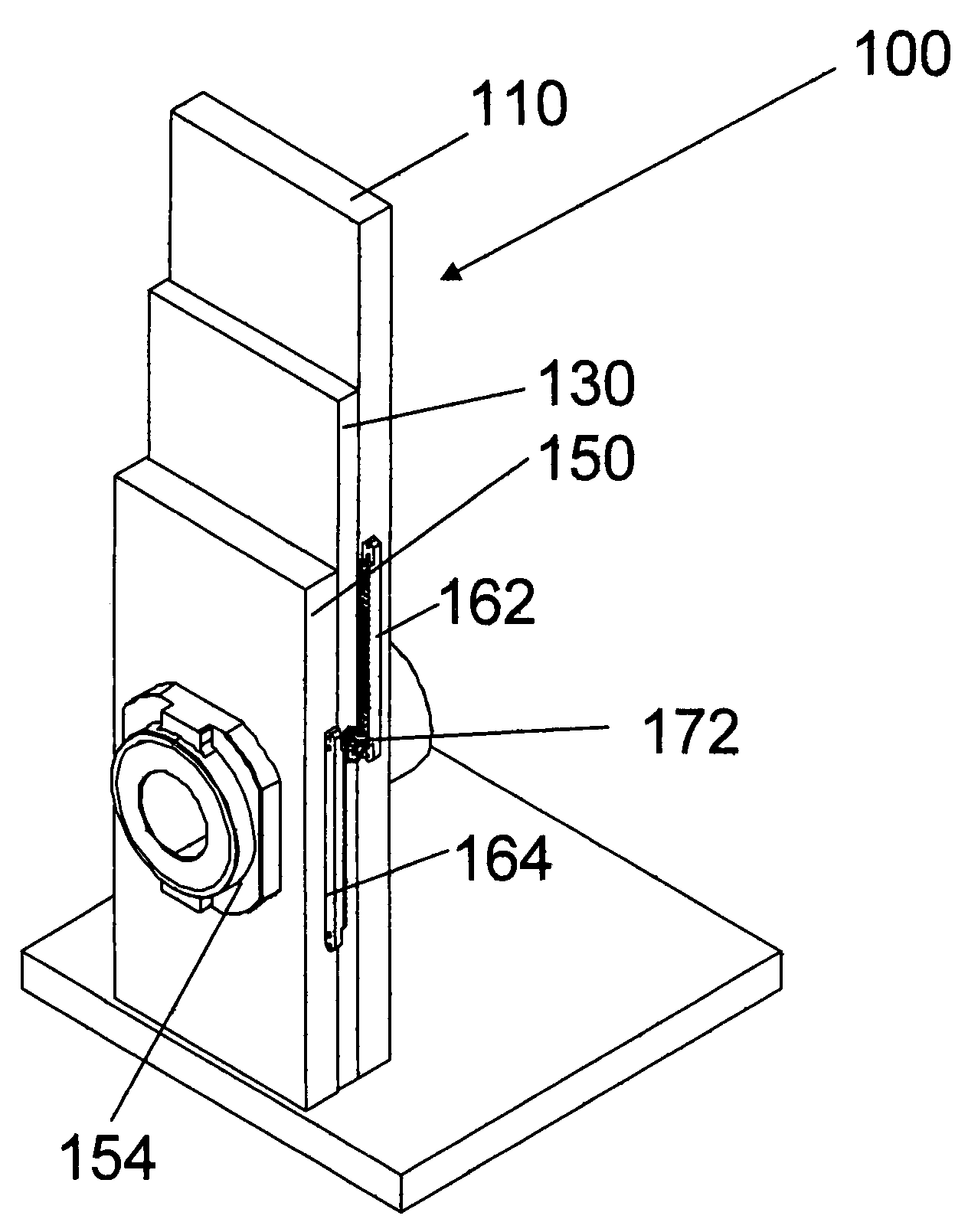
[0074]The present invention is a compound sliding seal unit of markedly reduced height dimensions and overall size which is employed as a discrete subassembly for both the passage across and the at-will height adjustment of a mounted, optionally rotatable, rod-like member (or spindle) which passes through and extends from the atmospheric environment portion into the vacuum environmental portion of an ion implanter apparatus. The extended, optionally rotatable, rod-like member or spindle is typically fashioned as either a hollow tube or shaft (suitable for the passage of electrical components) and / or as a rotatable support bar or appendage (suitable for the mounting of a pivotal scanning radial arm translation system).

[0075]The manner of its construction and the substantially reduced height dimensions of the unique compound sliding seal unit comprising the present invention permits on-demand changes of height (elevation) for the mounted, optionally rotatable, rod-like member (or spin...


PUM


Abstract

The present invention is a compound sliding seal unit of markedly reduced size and height dimensions which is employed as a discrete assembly for both the passage across and the at-will height adjustment of a mounted, rotatable shaft which extends from the atmospheric environment portion into the vacuum environmental portion of an ion implanter apparatus. The extended, rotatable shaft is typically fashioned as either a rotatable hollow tube or conduit (suitable for the passage of electrical components) and / or as a rotatable support suitable for the mounting of a pivotal scanning radial arm translation system.The manner of construction and the substantially reduced height dimensions of the compound sliding seal unit permits on-demand changes of height for the mounted, rotatable shaft which extends from the atmospheric environment and extends through the compound unit into the confined and limited spatial volume of a vacuum environment within a conventional ion implantation apparatus. The compound unit also allows the user to maintain a high vacuum within the vacuum environment despite the fact that the height of the feed-through member can be raised and lowered repeatedly at will. Its compact size frees space which can be used to extend the vacuum chamber for purposes such as a deep Faraday cup for beam measurement.

Description

CROSS-REFERENCES & PRIORITY CLAIM[0001]This application is a Continuation-In-Part of U.S. patent application Ser. No. 11 / 209,484, filed on Aug. 22, 2005, entitled “Apparatus and Methods for Ion Beam Implantation”, now pending; which is a Continuation of U.S. patent application Ser. No. 11 / 123,924, filed on May 6, 2005, now U.S. Pat. No. 7,112,789. The legal priority of these previously filed applications is expressly claimed; and each of these previously filed applications, in its entirety, is expressly incorporated by reference herein.FIELD OF THE INVENTION[0002]The present invention relates generally to apparatus for performing ion implantation; and is directed to an improved compound sliding seal unit suitable for use in the vacuum conditions implantation apparatus and methods for performing a high / medium current ion implantation at different ion energies.BACKGROUND OF THE INVENTION[0003]Ion implantation is a ballistic process used to introduce specific ion species, atoms or mole...

Claims


Application Information

Patent Timeline
Patent Type & Authority Applications(United States)
IPC IPC(8): F16J15/32
CPCH01J37/20H01J2237/20228H01J2237/2006H01J37/3171Y10S277/911Y10S277/913
Inventor MCRAY, RICHARD F.WHITE, NICHOLAS R.
Owner ADVANCED ION BEAM TECHNOLOGY INC
Why Eureka
Try Eureka