Stepping motor

a technology of stepping motor and stepping shaft, which is applied in the direction of dynamo-electric machines, instruments, clocks, etc., can solve the problems of difficult standardization of production procedures and the structure of motors, and achieve the effect of maximizing the motor torque and the ratio of a volume of the coil

Inactive Publication Date: 2009-03-12
MINEBEA CO LTD
View PDF8 Cites 15 Cited by
  • Summary
  • Abstract
  • Description
  • Claims
  • Application Information

AI Technical Summary

Benefits of technology

[0034]With this structure, the bearing can be reliably prevented from coming off the first yoke.
[0035]Accordingly, in the stepping motor according to the present invention, the ratio of a volume of the coil can be maximized relative to the motor axial dimension thereby maximizing the motor torque, which is favorable when the stepping motor has an upper limits to its axial dimension.

Problems solved by technology

Also, since the front plate 20 functions as a motor attachment plate and has its configuration modified according to customers' specifications, different production procedures are required for the different configurations of the front plate 20, which makes it difficult to standardize the production procedure, and the motor structure as well.

Method used


Image

  • Stepping motor
  • Stepping motor
  • Stepping motor

Examples


first embodiment

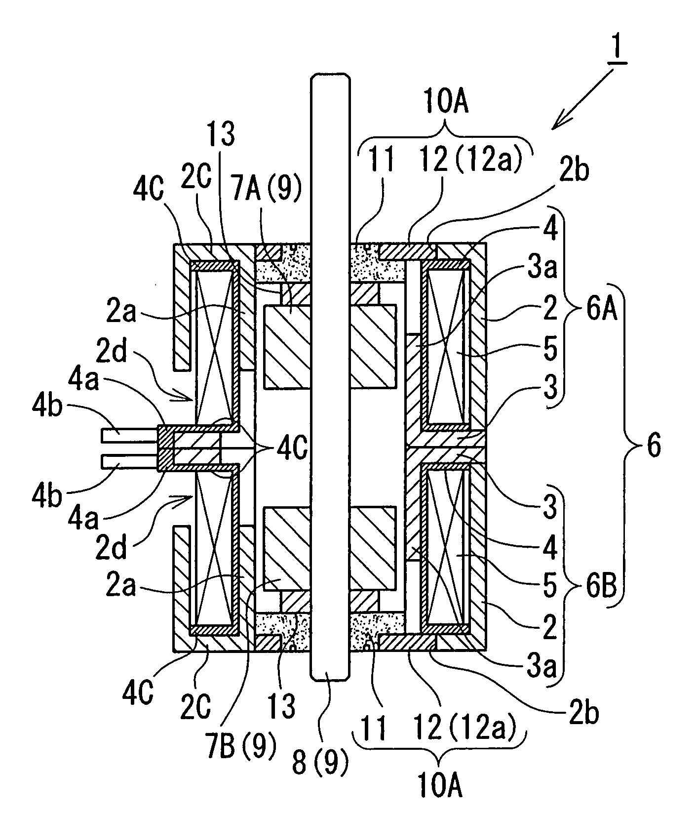
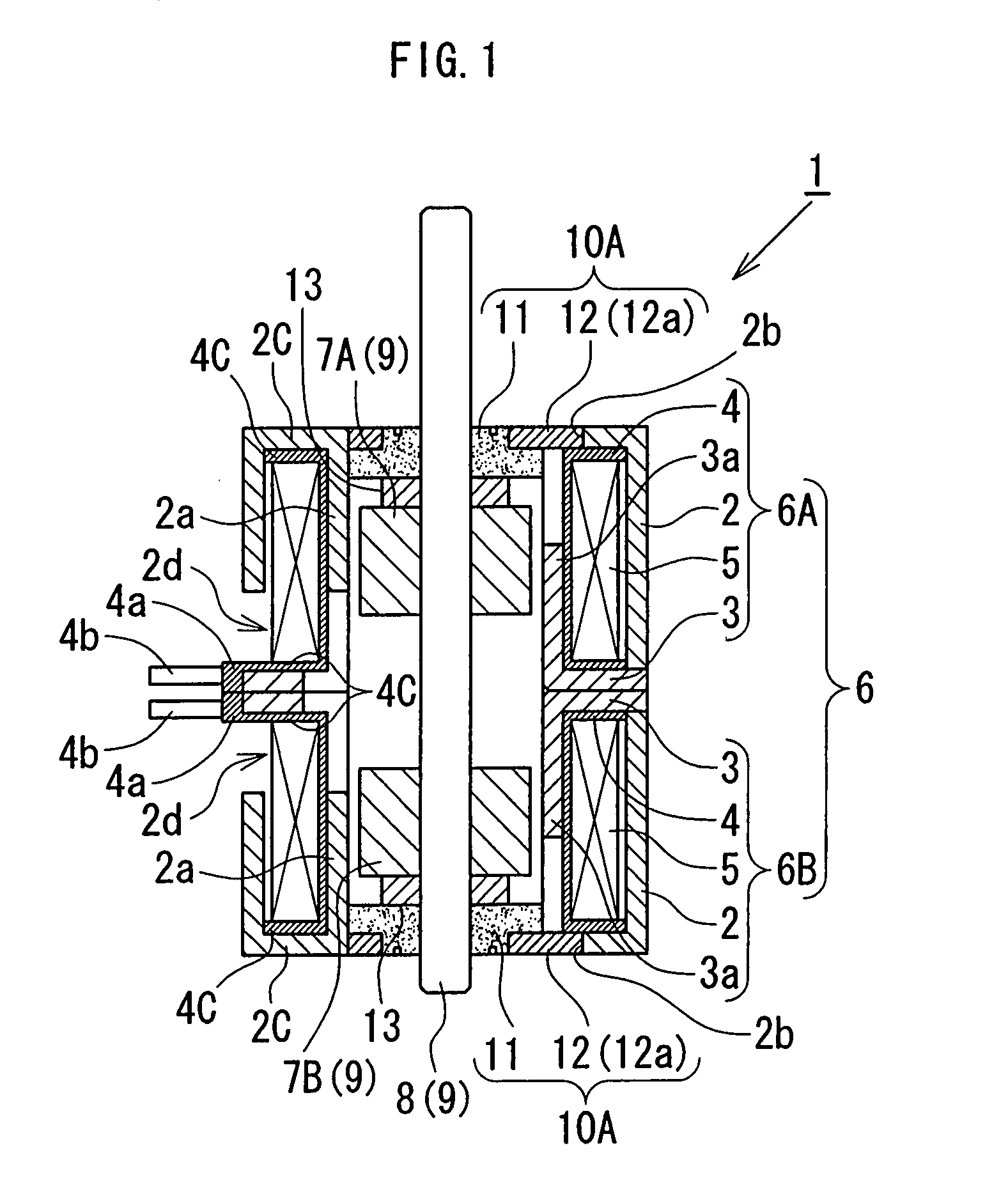
[0051]the present invention will be described with reference to FIGS. 1 to 9. Referring to FIG. 1, a stepping motor 1 according to the first embodiment basically includes a stator assembly 6 and a rotor assembly 9.

[0052]The stator assembly 6 is made up of two stators 6A and 6B which are structured identically with each other and each structured such that a coil 5 wound around a bobbin 4 is housed in an annular hollow space formed by coupling of a first yoke 2 (outer yoke) and a second yoke 3 (inner yoke) which have respective pluralities of pole teeth 2a and 3a intermeshing with each other, wherein the two stators 6A and 6B are put together back to back with a phase difference of 90 degrees (electrical angle) therebetween thereby generating a two-phase magnetic field.

[0053]The rotor assembly 9 is made up of a rotary shaft 8, and rotor magnets 7A and 7B fixedly attached to the rotary shaft 8. The outer circumferences of the rotor magnets 7A and 7B are multipole-magnetized in the circ...

second embodiment

[0092]Referring to FIG. 10, a stepping motor 100 includes a bearing 10A which is structured identically with the bearing 10A of FIG. 1 and disposed in a stator 6B, and a bearing 10D which is different from the bearing 10A and disposed in a stator 6A. Referring to FIG. 11, the bearing 10D attached to a first yoke 2 of the stator 6A differs from the bearing 10A only in that the axial outer end (upper side in the figure) of the main body 11 is elevated compared to the outer faces of the protrusions 12a, rather than being flush therewith (refer to FIG. 5). That is to say, the bearing 10D has a larger axial dimension, for example by about 0.3 mm, than the bearing 10A, and when the bearing 10D is set in the first yoke 2 with the protrusions 12a making contact with a flange 4c of a bobbin 4, the elevated part of the main body 11 of the bearing 10D protrudes axially outwardly beyond a bottom plate 2c of the first yoke 2.

[0093]Accordingly, when a mounting plate (not shown) for attaching a m...


PUM


Abstract

A stepping motor includes: a stator which includes a cup-like first (outer) yoke having a plurality of notches formed at its bottom plate, a second (inner) yoke, and a bobbin having a coil wound therearound and housed in the annular hollow space formed by the first and second yokes; and a pair of bearings each of which includes a hollow-cylindrical main body and a flange structure having a plurality of protrusions, and is attached to the stator such that the protrusions engage with the notches of the first yoke thereby preventing the bearing from rotating relative to the first yoke, and such that the protrusions make contact with a flange of the bobbin thereby precisely positioning the bearing relative to the first yoke with respect to the axial direction, which prohibits any portions of the bearing from protruding axially outwardly beyond the bottom plate of the first yoke.

Description

BACKGROUND OF THE INVENTION[0001]1. Field of the Invention[0002]The present invention relates to a stepping motor, and more specifically to a PM (permanent magnet) type stepping motor.[0003]2. Description of the Related Art[0004]FIGS. 12 and 13 are respectively partly cutaway perspective and cross sectional views of a conventional PM stepping motor 30.[0005]The PM stepping motor (hereinafter referred to as “stepping motor” as appropriate) 30 includes a stator assembly composed of first and second stators fixedly attached to each other. The first stator includes a bobbin 33a, a coil 34a wound around the bobbin 33a, and first (outer) and second (inner) yokes 31a and 32a disposed to house the bobbin 33a and the coil 34a, and the second stator includes a bobbin 33b, a coil 34b, and first and second yokes 31b and 32b (outer and inner yokes) disposed to house the bobbin 33b and coil 34b. [0006]The stepping motor 30 also includes a rotor assembly composed of a ring magnet (permanent magnet...

Claims


Application Information

Patent Timeline
Patent Type & Authority Applications(United States)
IPC IPC(8): H02K37/12
CPCH02K5/1672H02K37/14H02K21/145
Inventor SUZUKI, YUZURUYAMAWAKI, TAKAYUKIFURUSAKI, HIROYUKIKAGAWA, MASAKI
Owner MINEBEA CO LTD
Why Eureka
Try Eureka