Method for automatic impedance matching for a radiofrequency circuit and transmission or reception system with automatic matching

a radio frequency circuit and automatic matching technology, applied in power amplifiers, modulation, amplifier input/output impedence modification, etc., can solve problems such as parasitic interference, loss of mismatch loss, and deterioration of performan

Active Publication Date: 2009-03-12
COMMISSARIAT A LENERGIE ATOMIQUE ET AUX ENERGIES ALTERNATIVES
View PDF9 Cites 72 Cited by
  • Summary
  • Abstract
  • Description
  • Claims
  • Application Information

AI Technical Summary

Benefits of technology

[0026]A measurement impedance of a known complex value is preferably inserted in series between the amplifier and the matching network; it enables determination of the current which will serve to calculate the complex impedance. This measurement impedance may be a simple capacitor.

Problems solved by technology

These variations in impedance may lead to losses called mismatch losses: these losses result from the fact that the transmission system that supplies the antenna, or the reception system that receives a signal from the antenna, is generally designed for optimal performance when it is loaded (at output for the transmission system or at input for the reception system) with a well determined nominal impedance.
Its performance deteriorates when it is loaded with an impedance different from its nominal value.
On the one hand, the reflected power may be low and subject to parasitic interference as all interference picked up by the antenna distorts the measurement due to the fact that it is added to the reflected power while it does not constitute power reflected by the mismatch.
This method therefore leads to an new impedance which is not necessarily optimal, as several complex impedance pairs correspond to a given power.
This is because detecting the mismatch through the power measurement (scalar method) causes a loss of information about the phase shift between the currents and voltages.
Finally, the bidirectional couplers it uses are bulky.
These systems are not well suited for applications where the matching speed and size are important criteria.

Method used


Image

  • Method for automatic impedance matching for a radiofrequency circuit and transmission or reception system with automatic matching
  • Method for automatic impedance matching for a radiofrequency circuit and transmission or reception system with automatic matching

Examples


Embodiment Construction

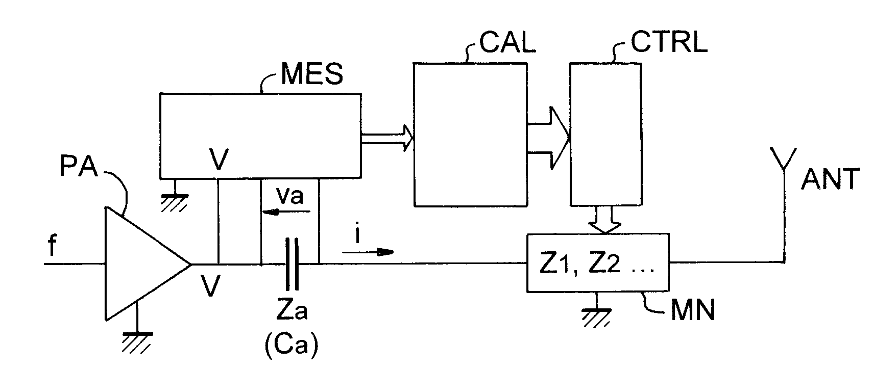
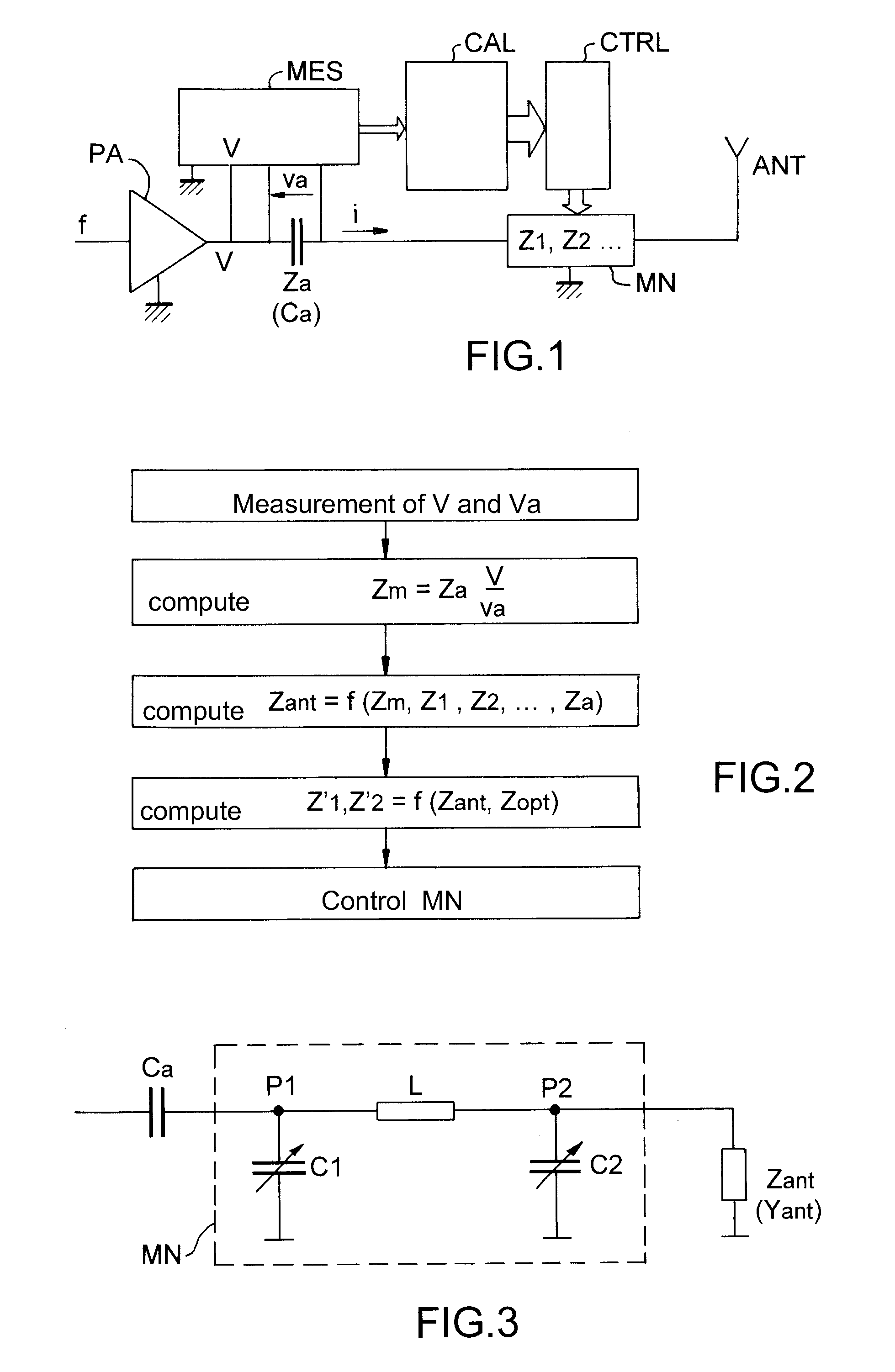
[0044]In the following detailed description the antenna will systematically be considered to be a transmit antenna supplied by the output from an amplifier which is designed to operate optimally when the load located at its output has a nominal impedance Zopt and when the operating frequency is f, corresponding to an angular frequency ω=2πf. At high frequencies, the impedance Zopt will generally be complex. But the invention is applicable in the same way if the antenna is a receive antenna connected to the input of an amplifier designed to operate optimally when the impedance connected to its input is a nominal impedance Zopt and when the operating frequency is f. If the antenna must simultaneously operate as a transmitter and as a receiver, the transmit amplifier will preferably have a nominal load impedance equal to the nominal input impedance of the receive amplifier. If this is not the case, the transmit amplifier and the receive amplifier will be associated with two distinct ma...


PUM


Abstract

The invention relates to a method for automatically matching the antenna impedance for a radiofrequency transmission circuit having an amplifier. An impedance matching network is inserted between the amplifier and the antenna. The output current i and voltage V from the amplifier and their phase shift are measured, and from this the complex impedance, defined by V/i, is deduced. The antenna impedance is calculated as a function of this complex impedance and as a function of the known present values of the adjustable impedances of the matching network. New values are calculated, from the calculated value of the antenna impedance, for the adjustable impedances of the matching network that allow an overall load impedance of the amplifier to be obtained which is as close as possible to the nominal load impedance Zopt of the amplifier, and the matching network is controlled to adjust the adjustable impedances to these new values.

Description

RELATED APPLICATIONS[0001]The present application is based on French, and claims priority from, French Application Number 07 06360, filed Sep. 11, 2007, the disclosure of which is hereby incorporated by reference herein in its entirety.FIELD OF THE INVENTION[0002]The invention relates to the production of an automatic impedance matching circuit for a radio antenna.BACKGROUND OF THE INVENTION[0003]In some radiofrequency information transmission applications it has been observed that the transmit or receive antenna might have an impedance depending strongly on conditions external to the antenna, and depending notably on the environment in which the antenna is placed.[0004]For example, in medical telemetry it is possible for an antenna in a probe to be placed inside the human body, and the impedance then depends strongly on the biological environment in which the antenna finds itself. It depends on the electrical properties (conductivity, dielectric constant) of the surrounding tissues...

Claims


Application Information

Patent Timeline
Patent Type & Authority Applications(United States)
IPC IPC(8): H03H7/40
CPCH03F1/56H03F3/24H03F2200/378H04B1/0458H03F2200/451H03H7/40H03F2200/387
Inventor CHAN WAI PO, FRANCISDE FOUCAULD, EMERICVINCENT, PIERRE
Owner COMMISSARIAT A LENERGIE ATOMIQUE ET AUX ENERGIES ALTERNATIVES
Why Eureka
Try Eureka