Lens for use with a light-emitting element and light source device including the lens

a light-emitting element and light-emitting diode technology, applied in the field of lenses, can solve the problems of large power consumption, large size of cold cathode fluorescent lamps, and large environmental impact, and achieve the effect of uniform distribution of light intensity

Inactive Publication Date: 2009-03-12
BRIGHT LED ELECTRONICS CORP
View PDF24 Cites 16 Cited by
  • Summary
  • Abstract
  • Description
  • Claims
  • Application Information

AI Technical Summary

Benefits of technology

[0007]Therefore, an object of the present invention is to provide a lens for use with a light-emitting element so as to obtain a relatively even distribution of a light intensity.

Problems solved by technology

However, the cold cathode fluorescent lamp has drawbacks of a relatively large size, large power consumption, and use of mercury that is detrimental to the environment.
Therefore, the distribution of the light intensity on the light-exiting surface of the conventional light-emitting diode is relatively uneven.

Method used


Image

  • Lens for use with a light-emitting element and light source device including the lens
  • Lens for use with a light-emitting element and light source device including the lens
  • Lens for use with a light-emitting element and light source device including the lens

Examples


Embodiment Construction

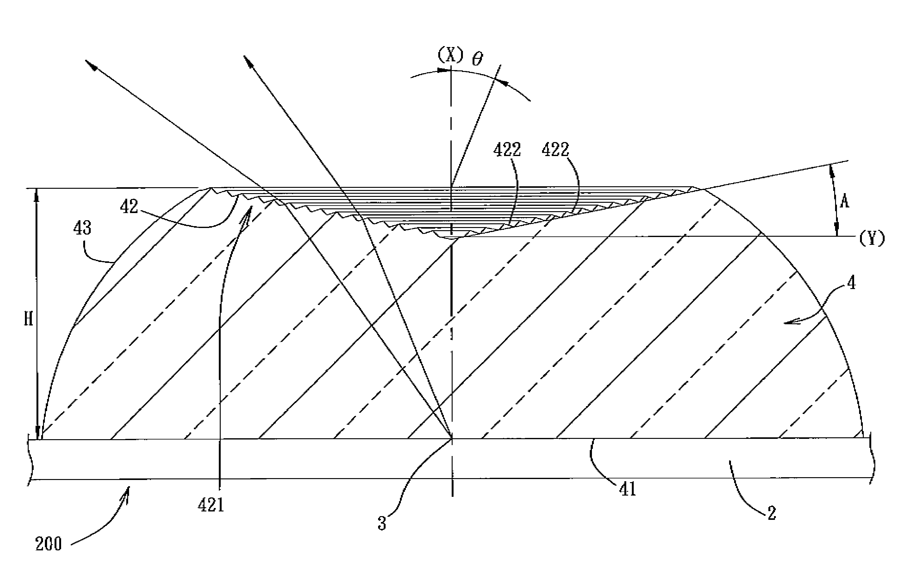
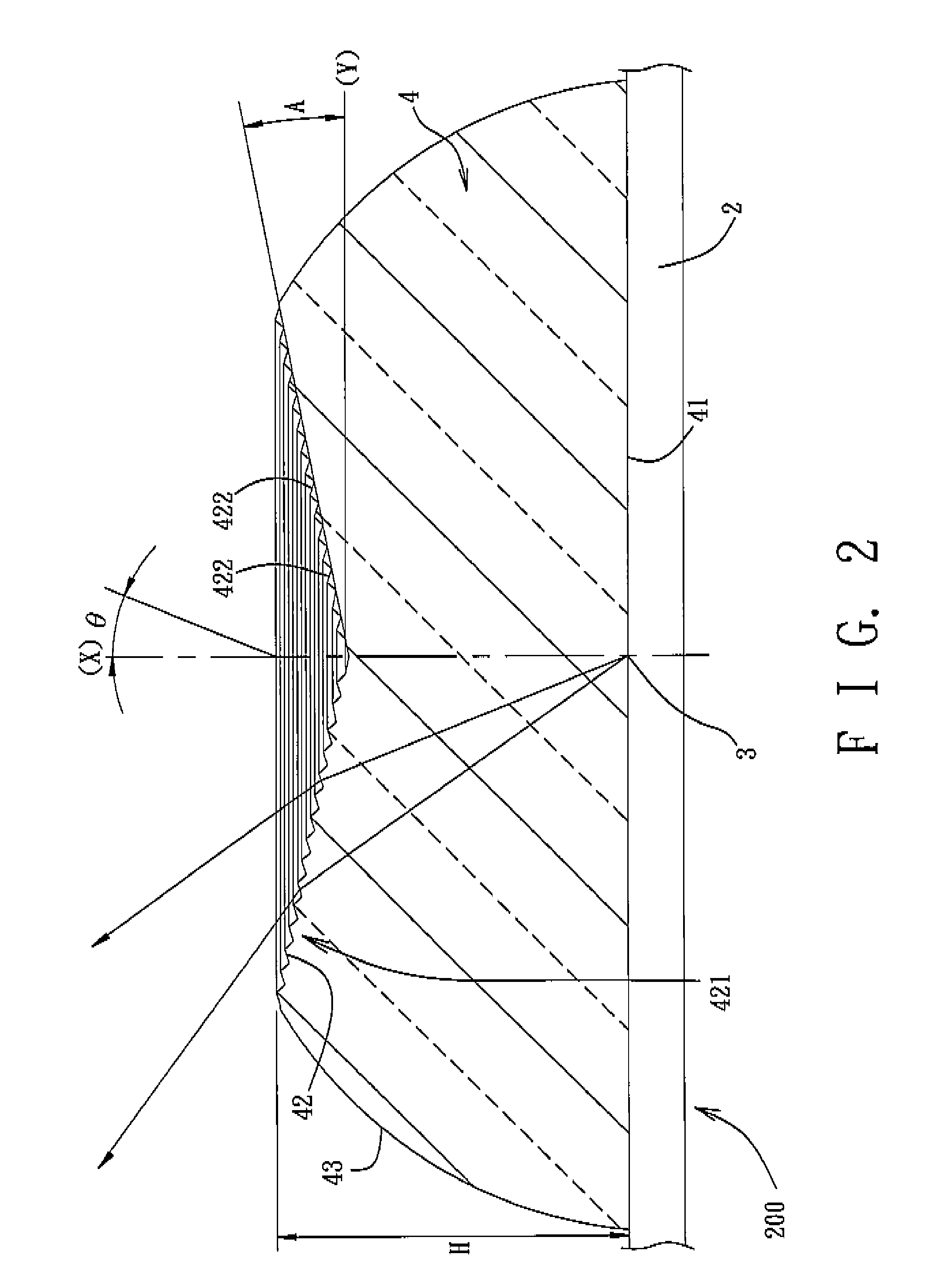
[0025]Referring to FIGS. 2, 3, 4, and 5, the preferred embodiment of a lens 4 according to this invention is used in a light source device 200, which includes a base 2, a light-emitting element 3 mounted on the base 2, and the lens 4 mounted on the base 2.

[0026]The base 2 can be any base commonly used in the art of packaging a light-emitting semiconductor component, and examples thereof include a plastic coated metal lead frame, a vertical lead frame, a planar lead frame, a piranha lead frame, or the like. The light-emitting element 3 is mounted by die-attaching, wire-bonding, and packaging. The light-emitting element 3 used in the preferred embodiment is a light-emitting diode.

[0027]The lens 4 is mounted on the base 2 and encapsulates the light-emitting element 3. The lens 4 can be made by injection molding of a thermoplastic polymer, such as polymethyl methacrylate, polycarbonate, or the like, by infusion of thermosetting plastic, such as epoxy resin, silicone, or the like, or by ...


PUM


Abstract

A lens for use with a light-emitting element includes a lens body that has a bottom surface for receiving light from the light-emitting element, a top surface opposite to the bottom surface along an optical axis, a peripheral surface extending and converging from the bottom surface to the top surface such that a projection of a perimeter of the top surface onto a plane of the bottom surface is surrounded by a perimeter of the bottom surface, and a textured structure formed on the top surface for scattering light that exits the top surface at angles relative to the optical axis.

Description

CROSS-REFERENCE TO RELATED APPLICATION[0001]This application is a continuation-in-part of pending U.S. patent application Ser. No. 11 / 619,704, filed on Jan. 4, 2007, and claims priority of Taiwanese Application No. 096143213, filed on Nov. 15, 2007.BACKGROUND OF THE INVENTION[0002]1. Field of the Invention[0003]The invention relates to a lens, more particularly to a lens for use with a light-emitting element. The invention also relates to a light source device including the lens.[0004]2. Description of the Related Art[0005]It is conventional to use a cold cathode fluorescent lamp as a light source in a direct-type backlight module. However, the cold cathode fluorescent lamp has drawbacks of a relatively large size, large power consumption, and use of mercury that is detrimental to the environment. Therefore, it has become a trend to substitute the cold cathode fluorescent lamp with a light-emitting diode, which has advantages such as a relatively small size, a high light-emitting ef...

Claims


Application Information

Patent Timeline
Patent Type & Authority Applications(United States)
IPC IPC(8): F21V14/00
CPCG02B5/045G02B17/086G02B27/095G02B19/0061H01L33/58G02B19/0071G02B19/0028H01L33/54
Inventor CHEN, LIANG-TANGCHANG, MING-LIYIN, CHOU-CHIH
Owner BRIGHT LED ELECTRONICS CORP
Why Eureka
Try Eureka