Modeling sound propagation for underwater test areas

a technology for underwater test areas and sound propagation, applied in the field of modeling sound propagation, can solve problems such as adversely affecting the validity of test events, affecting sound propagation, and difficult detection of sound reflective objects

Inactive Publication Date: 2009-03-12
THE UNITED STATES OF AMERICA AS REPRESENTED BY THE SECRETARY OF THE NAVY +1
View PDF18 Cites 26 Cited by
  • Summary
  • Abstract
  • Description
  • Claims
  • Application Information

AI Technical Summary

Benefits of technology

[0033]The output of the present invention is a ray trace plot that provides a “snapshot” of the existing sound propagation paths for a specified depth. This enables a test team to assess the potential impact the modeled acoustic environment will have on the scheduled test events, (i.e., the detection performance of the underwater sound transmitting and receiving equipment being tested), prior to conducting a test.
[0034]The system and method of the present inve...

Problems solved by technology

However, the ocean environment is not isotropic, so sound waves emitted from a sound source do not propagate through the water in a linear fashion due to differences in temperature and pressure in the underwater environment.
The refraction or bending of the sound waves may cause detection “blind spots” where detection of a sound reflective object is precluded because the sound waves emitted from the sound source are unable to reach a specific area or sound waves reflecting off of a sound reflective object are unable to return to the sound source receiver location.
Further, the surrounding acoustic environment also affects sound propagation and the detectability of sound traveling through the water.
The surrounding acoustic environment variables typically attenuate the power of a sound wave originating from the sound source and mask any active sonar returning sound waves, making detection of the sound reflective object difficult.
The variability of the acoustic environment in a controlled environment, such as an underwater test range, results in uncertainties in the expected acoustic sound propagation paths, which may adversely impact the validity of test events designed to objectively test the ability of an underwater sound transmitting and receiving system under test to detect a sound reflective target object.
Each of these models is subject to and limited by computational errors associated with the complex mathematical alg...

Method used


Image

  • Modeling sound propagation for underwater test areas
  • Modeling sound propagation for underwater test areas
  • Modeling sound propagation for underwater test areas

Examples


Embodiment Construction

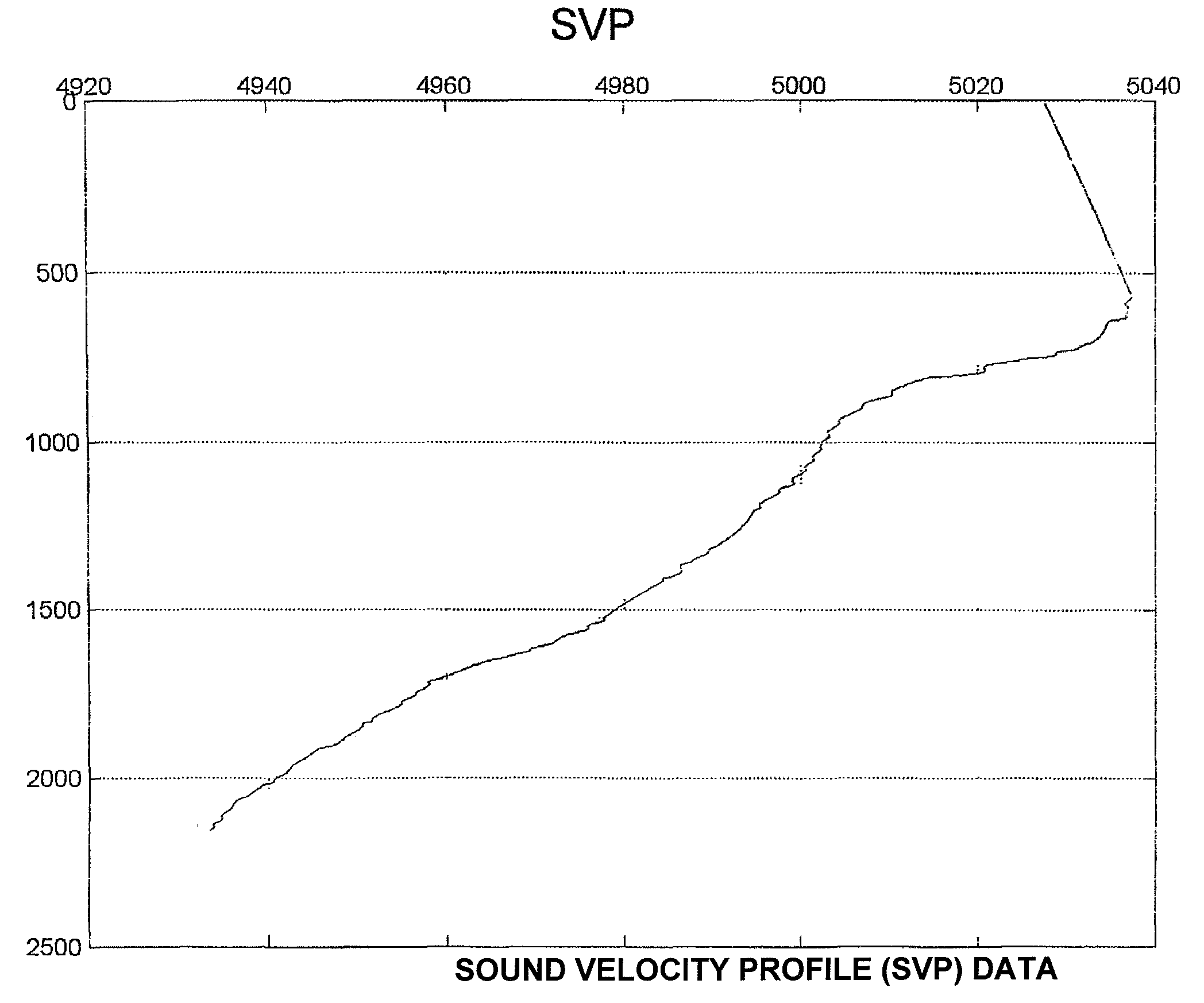
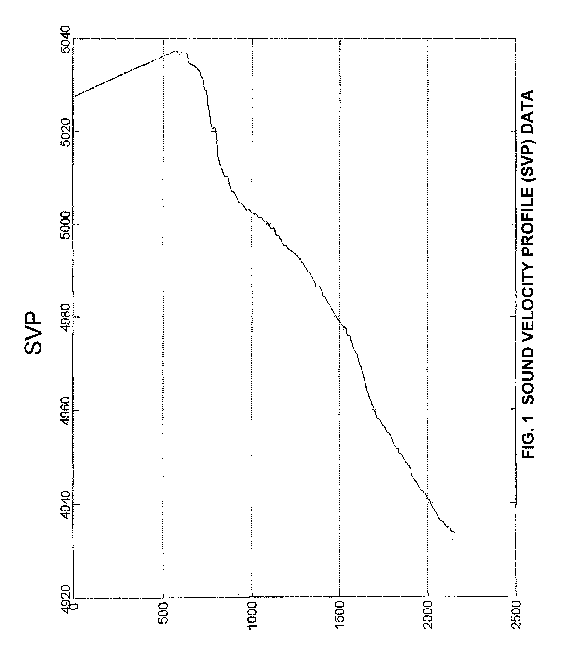
[0071]The system and method of the present invention quickly determine the ideal acoustic sound wave propagation paths available in the underwater test area by applying Snell's law to a current acoustic environment model based only on the current SVP data input and position of the sound source.

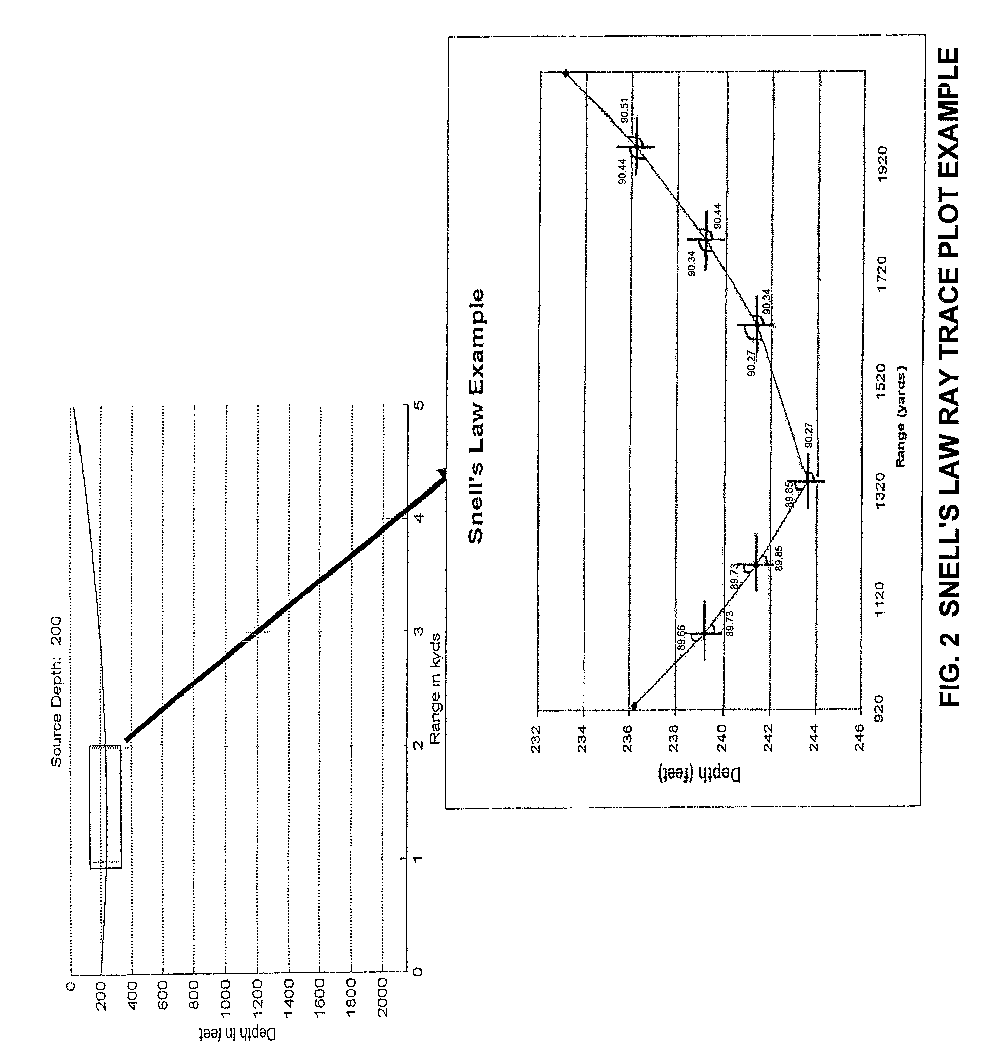
[0072]The system and method of the present invention uses the concept of sound rays to characterize the refraction of the sound waves in a body of water, such as the waters of a test area based on sound speed data. A sound ray is a vector that is perpendicular to the wave front and points in the direction in which the sound propagates. A ray trace is a line that traces a collection of sound rays over a propagation path. Ray traces represent the most probable paths sound waves emitted from a sound source at a specified depth will follow based on the current acoustic conditions. This ray method closely approximates actual propagation paths for wavelengths much less than the height of the water c...


PUM


Abstract

A system and method for quickly modeling the ideal acoustic sound propagation in a body of water based on current SVP data and the position of the sound source, comprising the steps of: obtaining SVP data for the body of water; determining a depth of a sound source within the body of water; selecting a first ray angle originating from the sound source; calculating a first ray trace for the first ray angle using only the SVP data as environmental inputs; repeating the selecting and calculating steps for second-nth ray angles to calculate second-nth ray traces for the second-nth ray angles; and plotting the first-nth ray traces to create a ray trace plot for the body of water relative to the depth of the sound source.

Description

STATEMENT OF GOVERNMENT INTEREST[0001]The Government of the United States of America has rights in this invention pursuant to Contract No. N00019-93-C-0196, awarded by the United States Navy (USN).FIELD OF THE INVENTION[0002]This invention relates generally to modeling sound propagation in a body of water, and specifically to modeling sound propagation in an underwater acoustic test environment using only sound velocity profile data and depth as input data.BACKGROUND OF THE INVENTION[0003]Sound transmitting and receiving equipment, such as sonar, is used in an underwater environment to detect sound reflective objects that are on the surface or below the surface of the water. Sonar systems can be broadly divided into two types: active sonar and passive sonar. An underwater sound source, such as active sonar, includes a transmitter that emits a sound wave that can be reflected off of a sound reflective object and a receiver that detects and measures the time of reception of the reflec...

Claims


Application Information

Patent Timeline
IPC IPC(8): G01S15/88
CPCG01S7/52004
Inventor LONDO, SHAWN P.MARTZ, MATTHEW A.
Owner THE UNITED STATES OF AMERICA AS REPRESENTED BY THE SECRETARY OF THE NAVY
Why Eureka
Try Eureka