Methods of emitter formation in solar cells

Inactive Publication Date: 2009-03-12
APPLIED MATERIALS INC
View PDF9 Cites 95 Cited by
  • Summary
  • Abstract
  • Description
  • Claims
  • Application Information

AI Technical Summary

Benefits of technology

[0012]The present invention also provides a method of forming a solar cell device, comprising forming a dielectric layer on a surface of a substrate, removing a portion of the dielectric layer from the surface to expose a portion of the substrate, disposing a first amount of a first dopant within a region of the substrate which is adjacent to

Problems solved by technology

Even small improvements in cost per Watt substan

Method used


Image

  • Methods of emitter formation in solar cells
  • Methods of emitter formation in solar cells
  • Methods of emitter formation in solar cells

Examples


Embodiment Construction

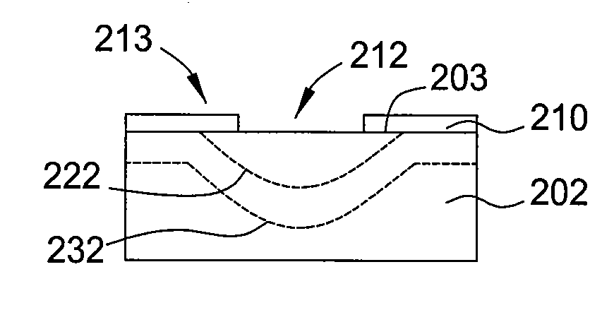
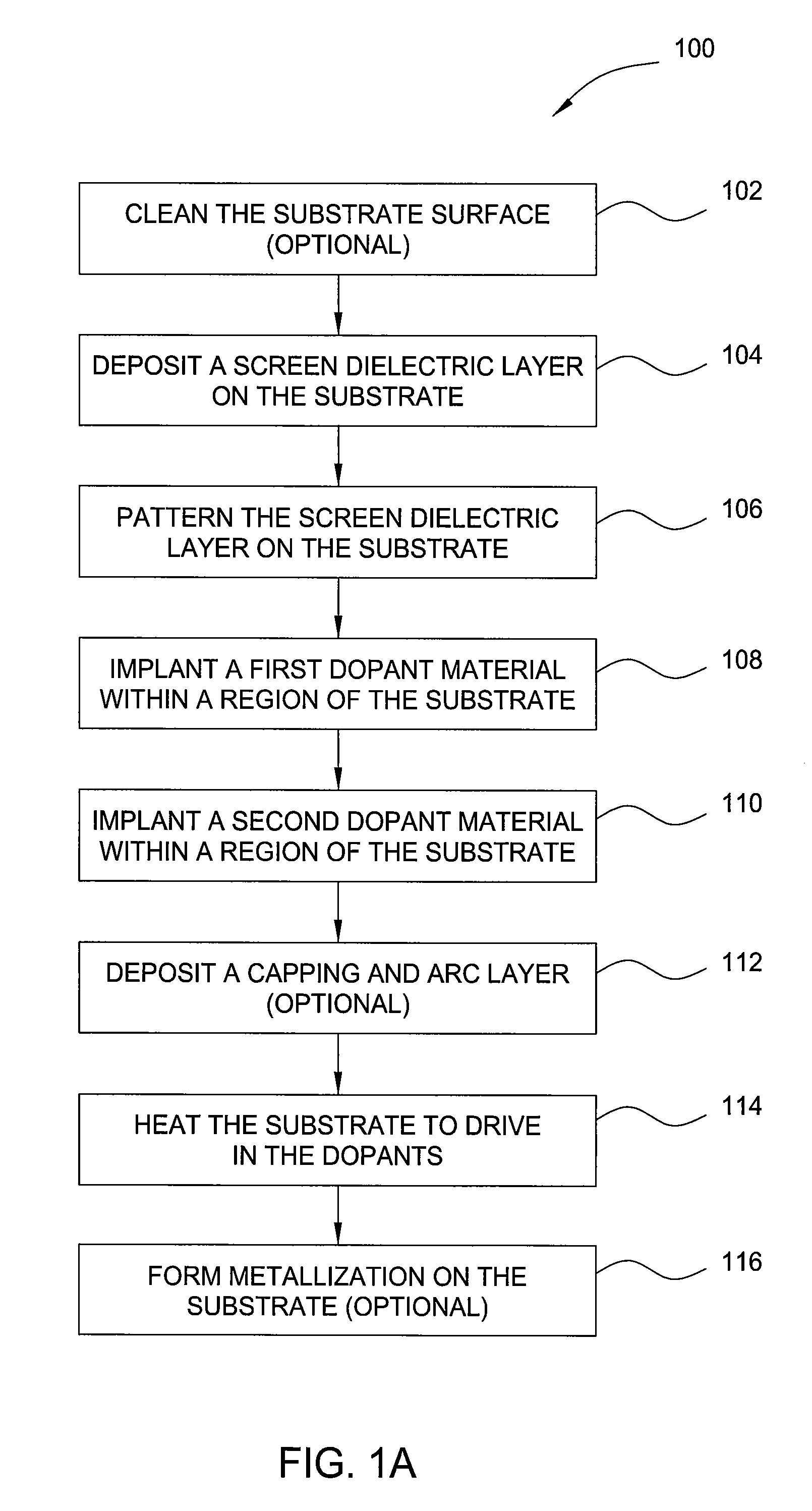
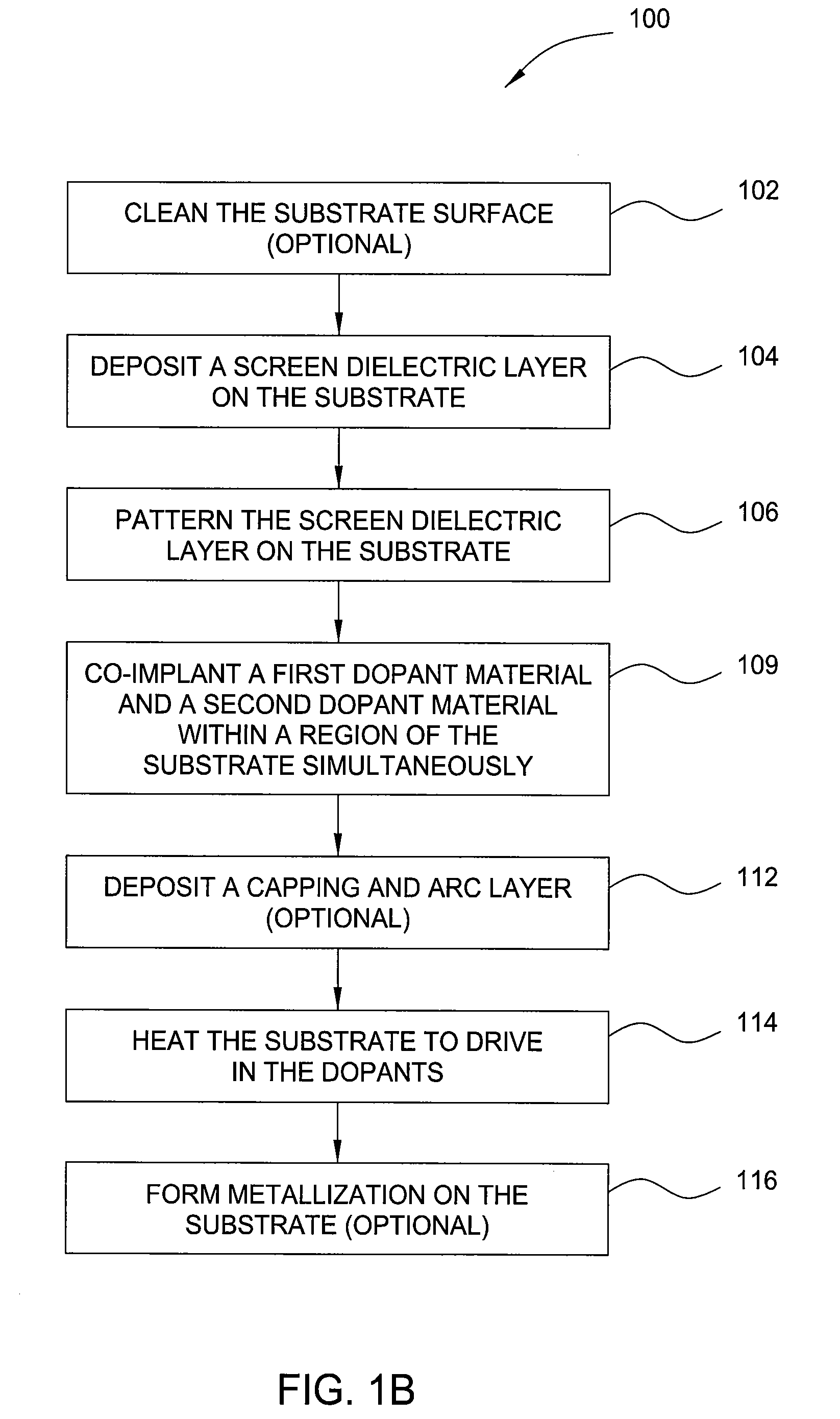
[0026]Embodiments of the invention contemplate the formation of high efficiency solar cells and novel methods for forming the same. One embodiment of the solar cell and improved emitter structure, called a high-low type emitter, is created to optimize the solar cell performance by equally providing low contact resistance to minimize ohmic losses and isolation of the high surface recombination metal-semiconductor interface from the junction to maximize cell voltage. Another embodiment of the improved emitter structure, called an alternating doping type emitter, provides regions of alternating doping type for use with point contacts in the back-contact solar cells. One embodiment of the methods for forming an improved emitter structure includes depositing and patterning a layer of dielectric material on a surface of a solar cell substrate, implanting a fast-diffusing dopant and a slow-diffusing dopant into the substrate either simultaneously or sequentially, and annealing the substrat...


PUM


Abstract

Embodiments of the invention contemplate high efficiency emitters in solar cells and novel methods for forming the same. One embodiment of the improved emitter structure, called a high-low type emitter, optimizes the solar cell performance by equally providing low contact resistance to minimize ohmic losses and isolation of the high surface recombination metal-semiconductor interface from the junction to maximize cell voltage. Another embodiment, called an alternating doping type emitter, provides regions of alternating doping type for use with point contacts in the back-contact solar cells. One embodiment of the methods includes depositing and patterning a doped or undoped dielectric layer on a surface of a substrate, implanting a fast-diffusing dopant and/or a slow-diffusing dopant into the substrate either simultaneously or sequentially, and annealing the substrate to drive in the dopants. Another embodiment of the methods includes using a physical mask to form a patterned dopant distribution in a substrate.

Description

CROSS-REFERENCE TO RELATED APPLICATIONS[0001]This application claims the benefit of U.S. Provisional Patent Application Ser. No. 60 / 959,583, filed Aug. 31, 2007 (Attorney Docket No. APPM / 012705L), which is herein incorporated by reference in its entirety.BACKGROUND OF THE INVENTION[0002]1. Field of the Invention[0003]Embodiments of the present invention generally relate to solar / photovoltaic cells and the method of forming selective emitters for the same.[0004]2. Description of the Related Art[0005]Solar or photovoltaic cells are material junction devices which convert sunlight into direct current (DC) electrical power. When exposed to sunlight (consisting of energy from photons), the electric field of solar cell p-n junction separates pairs of free electrons and holes, thus generating a photo-voltage. A circuit from p-side to n-side allows the flow of electrons when the solar cell is connected to an electrical load, while the area and other parameters of the SOLAR cell junction dev...

Claims


Application Information

Patent Timeline
IPC IPC(8): H01L31/18
CPCH01L31/022425H01L31/028Y02E10/547H01L31/1804H01L31/1864H01L31/068Y02P70/50
Inventor BORDEN, PETER
Owner APPLIED MATERIALS INC
Why Eureka
Try Eureka