Vibration suppressing device for machine tool

a technology of vibration suppressing device and machine tool, which is applied in the direction of feeding apparatus, fluid pressure measurement by mechanical elements, special data processing applications, etc., can solve the problems of generating a larger chatter vibration and unable to suppress chatter vibration, so as to achieve safe and effective suppression of chatter vibration, the effect of maintaining high finishing accuracy of the machined surfa

Inactive Publication Date: 2009-03-12
OKUMA CORP +1
View PDF11 Cites 24 Cited by
  • Summary
  • Abstract
  • Description
  • Claims
  • Application Information

AI Technical Summary

Benefits of technology

[0008]Therefore, an objective of the present invention is to provide a vibration suppressing device for a machine tool which can obtain an optimum rotation speed for respective cases where only the regenerative type chatter vibration is generated, only the forced chatter vibration is generated, and both the regenerative type chatter vibration and the forced chatter vibration are generated. Further, the vibration suppressing device can suppress a chatter vibration safely and effectively without one chatter vibration suppressing process exciting the other chatter vibration.
[0020]In addition to the effect of the second aspect, the inventions of the fifth and sixth aspects have the effect in which the optimum stable rotation speed can be calculated with respect to both the forced and regenerative type chatter vibrations without using any phase information.

Problems solved by technology

Therefore, there has been a problem that the chatter vibration cannot be suppressed or a bigger chatter vibration is generated.

Method used


Image

  • Vibration suppressing device for machine tool
  • Vibration suppressing device for machine tool
  • Vibration suppressing device for machine tool

Examples


Embodiment Construction

[0030]An embodiment of the present invention will be described below referring to the drawings.

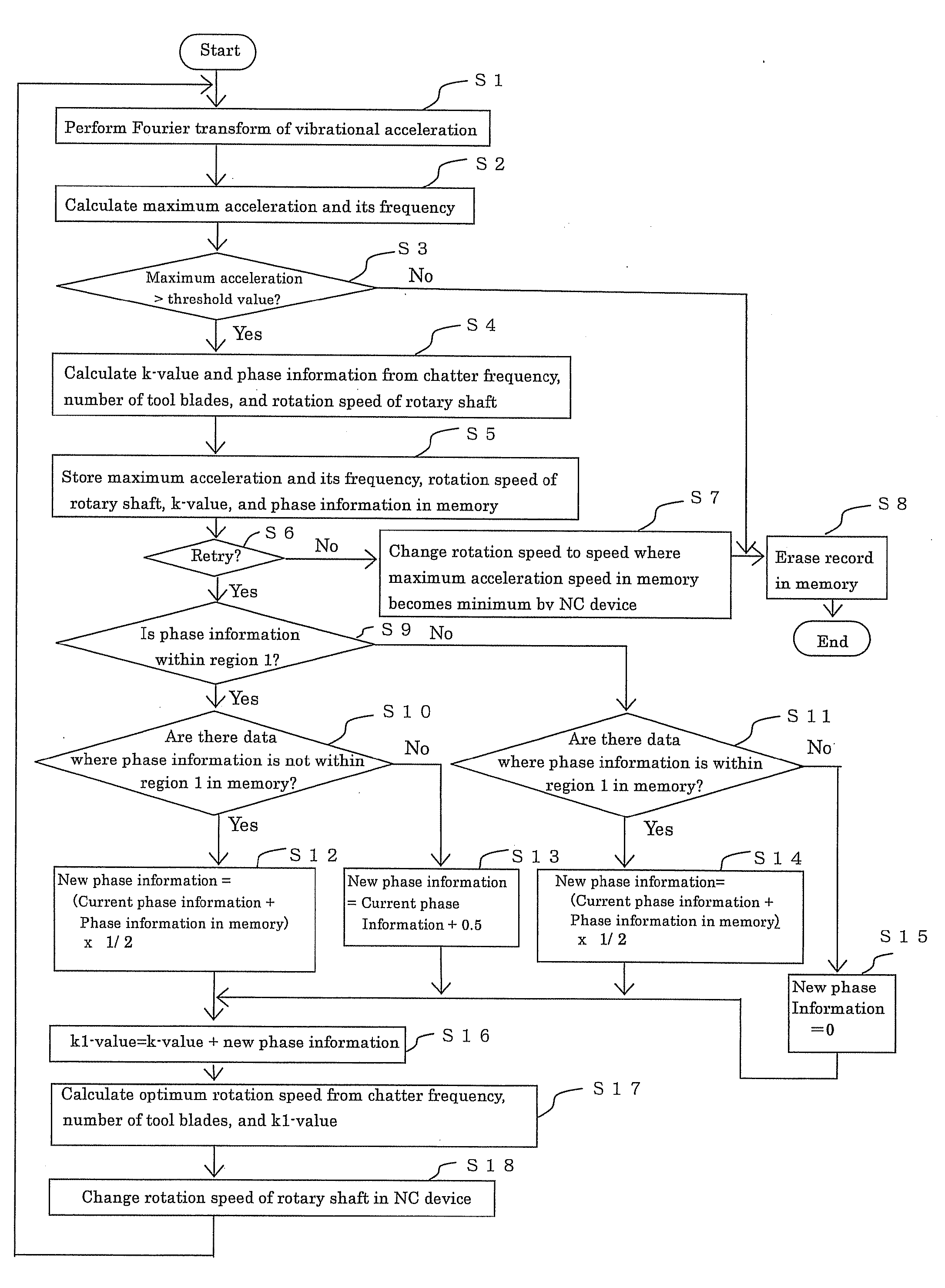
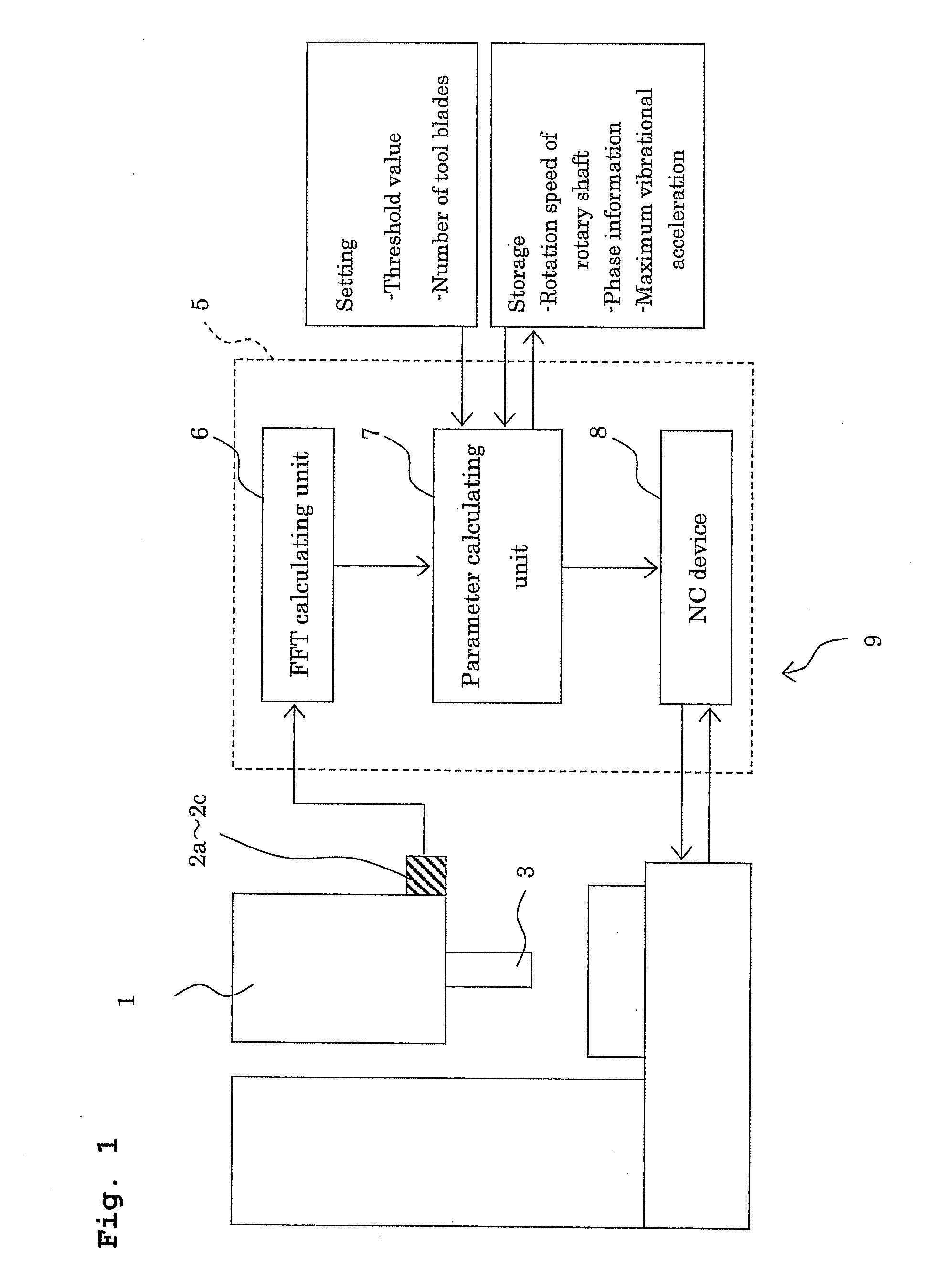
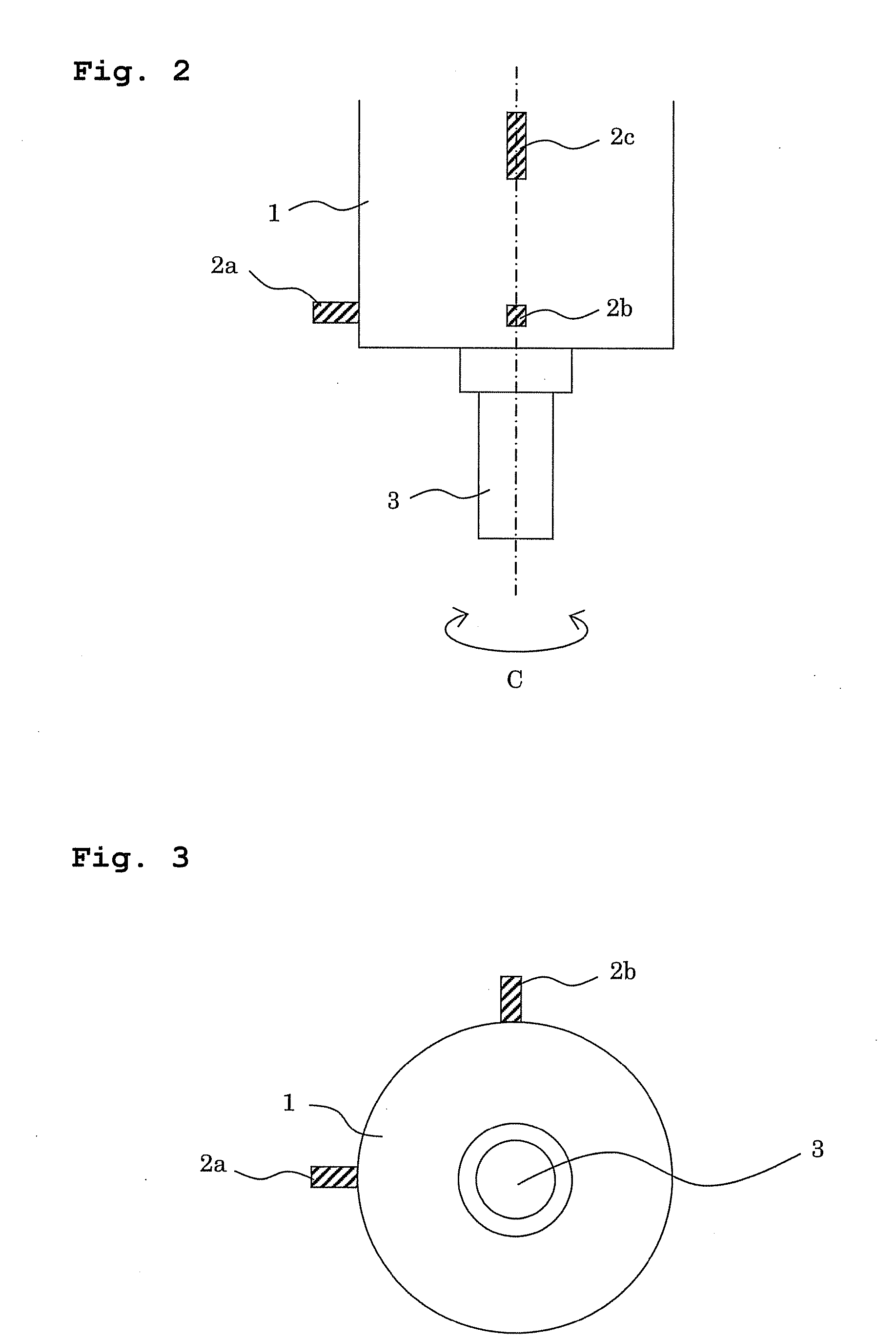
[0031]FIG. 1 is an explanatory diagram illustrating a block configuration of a vibration suppressing device. FIG. 2 is an explanatory diagram laterally illustrating a rotary shaft housing 1, which is subject to vibration suppression. FIG. 3 is an explanatory diagram illustrating the rotary shaft housing 1 in a shaft direction.

[0032]A vibration suppressing device 9 suppresses “chatter vibration” generated in a rotary shaft 3 rotatably provided around a C-axis of the rotary shaft housing 1. The vibration suppressing device 9 includes vibration sensors (detecting member) 2a to 2c for detecting time-domain vibrational accelerations generated at the rotating rotary shaft 3, and a control device (a calculating member and a rotation speed controlling member) 5 for controlling a rotation speed of the rotary shaft 3 based on values detected by the vibration sensors 2a to 2c.

[0033]The vibration sen...


PUM


Abstract

A calculating member carries out Fourier analysis of a vibrational acceleration to calculate a maximum acceleration and frequency thereof. The calculating member then compares the maximum acceleration with a threshold value, and when the acceleration exceeds the threshold value, the calculating member calculates a k-value and phase information, and stores each calculated value. When retrying is selected, the calculating member determines a type of a current chatter vibration from the phase information, determines the existence of a chatter vibration which is different from the determined chatter vibration, and calculates each new phase information according to the determined chatter vibration and an existence of a different chatter vibration which had been generated before generation of the current vibration. The calculating member then calculates a k1-value from new phase information, calculates the optimum rotation speed by using the k1-value, and changes the rotation speed to the optimum rotation speed.

Description

[0001]This application claims the benefit of Japanese Patent Application Numbers 2007-231918 filed on Sep. 6, 2007, the entirety of which is incorporated by reference.BACKGROUND OF THE INVENTION[0002]1. Field of the Invention[0003]The present invention relates to a vibration suppressing device for suppressing a vibration generated during machining in a machine tool by rotating of a tool or a work.[0004]2. Description of the Background Art[0005]There has conventionally been a machine tool, for example, where a work is supported by a rotatable main spindle and machined while a tool is being fed to the work. In the machine tools, when a cutting depth in cutting procedure is very large, a so-called “chatter vibration” is generated during the machining, resulting in deterioration in finishing accuracy of a machined surface, rapid wearing of a tool, and chipping a tool. Particularly, a “regenerative type chatter vibration” as a self-excited vibration is generated between the tool and the ...

Claims


Application Information

Patent Timeline
Patent Type & Authority Applications(United States)
IPC IPC(8): G06F19/00B23Q11/00B23Q15/12B23Q17/12
CPCB23Q11/0039F16F15/002B23Q17/0976
Inventor SUZUKI, NORIKAZUSHAMOTO, EIJIHAMAGUCHI, AKIHIDE
Owner OKUMA CORP
Why Eureka
Try Eureka