Control method for robots

a robot and control method technology, applied in the field of industrial robot systems, can solve the problems of increasing tcp errors, time-consuming procedures, and increasing the accuracy of initial defined tcp, and achieve the effect of accurate, fast and robus

Inactive Publication Date: 2009-03-12
ABB (SCHWEIZ) AG
View PDF14 Cites 36 Cited by
  • Summary
  • Abstract
  • Description
  • Claims
  • Application Information

AI Technical Summary

Benefits of technology

[0021]A first object of the invention is to provide a method which eliminates both the use of a gun equalizer and the need for manua

Problems solved by technology

The first procedure is time consuming and the second procedure is faster but every spot has to be corrected manually by jogging the robot to the exact position the real cell due to differences between the simulation and the real world.
During spot welding the welding tips of the electrodes wear over time since some material burns away with every weld and consequently the originally defined TCP becomes more and more inaccurate.
Since the robot controller is not aware of this and the robot program is not modified accordingly, an increasing TCP error occurs.
Touching up this reference surface with a worn tip gives the tip wear as the difference between the expected contact point and

Method used


Image

  • Control method for robots
  • Control method for robots
  • Control method for robots

Examples


Embodiment Construction

[0053]The following description relates to both the method and to the device.

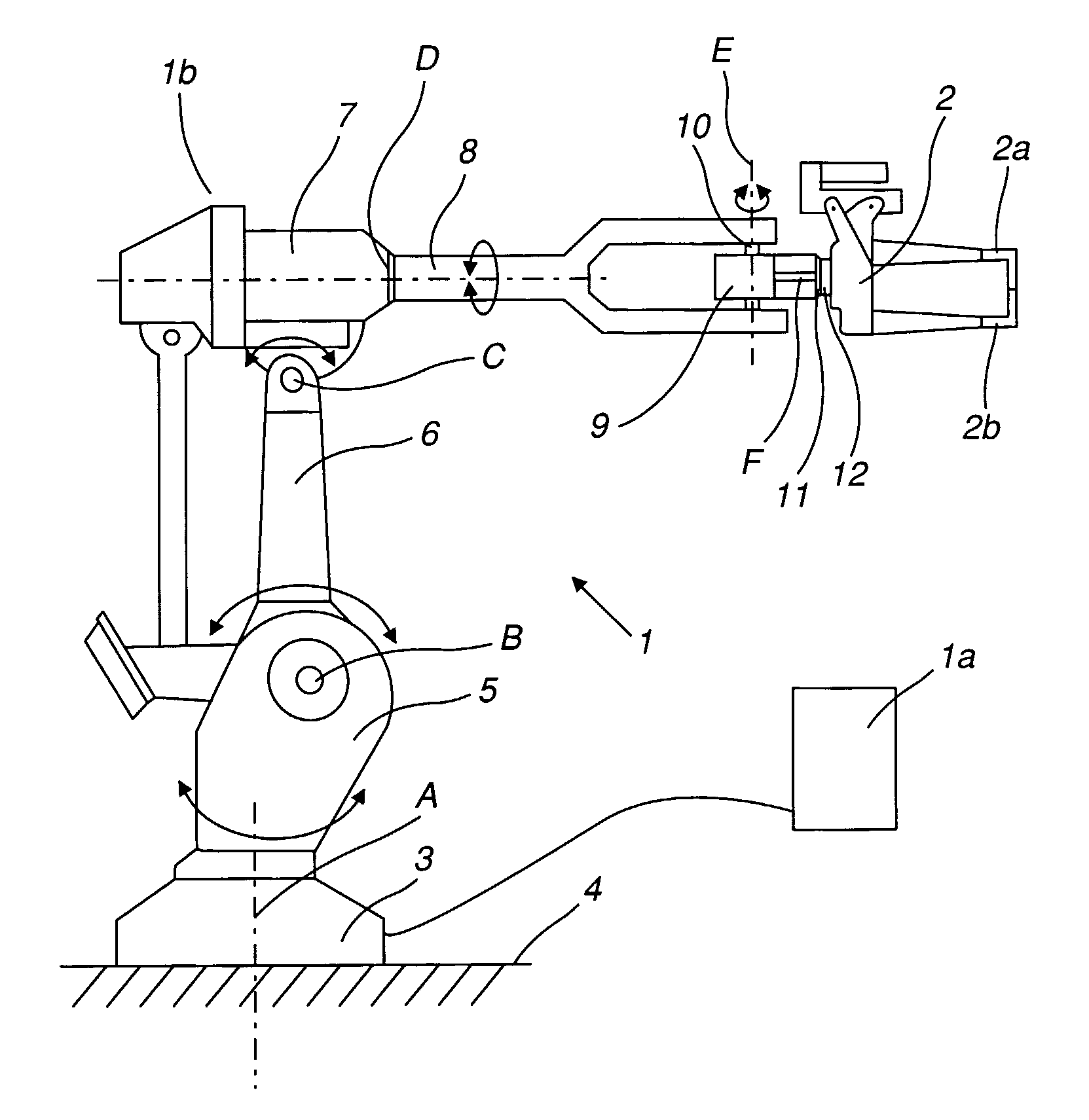
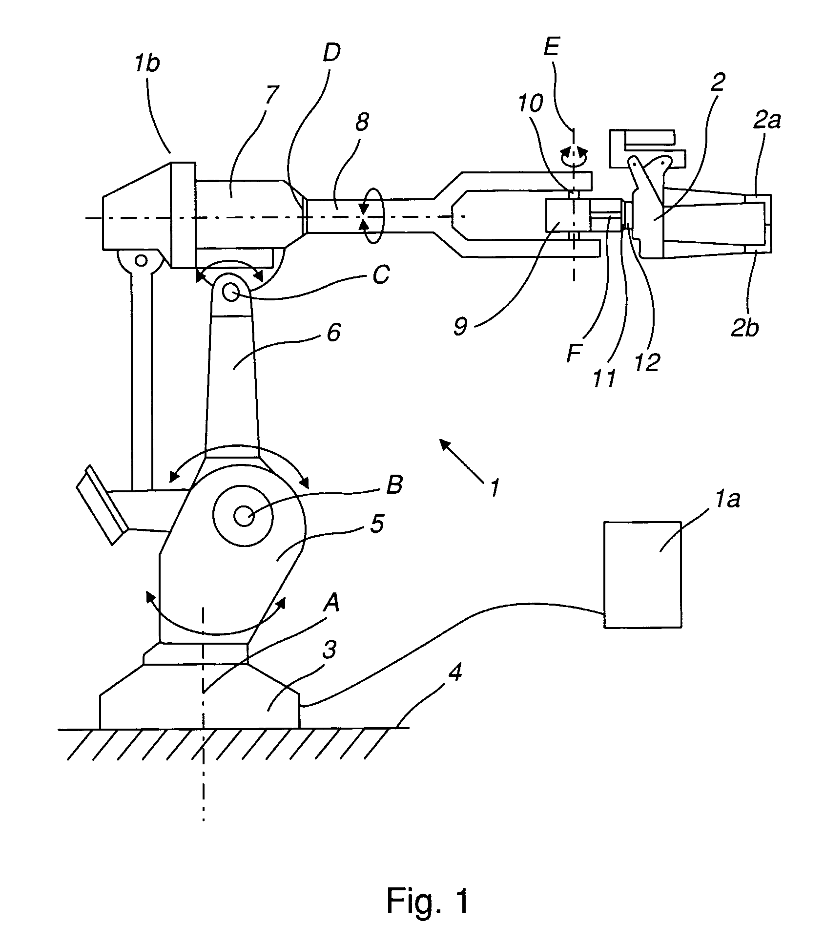
[0054]FIG. 1 is an industrial robot system comprising an industrial robot 1 with a control unit 1a, a manipulator 1b and a robot tool, a spot weld gun 2. The industrial robot comprises a foot 3 mounted to a base 4. The foot supports a stand 5, which is arranged to rotate in relation to the foot 3 about a first axis A. The stand 5 supports a first robot arm 6, arranged to rotate in relation to the stand 5 about a second axis B. The first robot arm supports an arm housing 7, which is arranged to rotate in relation to the first robot arm 5 about a third axis C. The arm housing 7 supports a second robot arm 8, arranged to rotate in relation to the arm housing 7 about a fourth axis D, and where the fourth axis D coincides with the longitudinal axis of the second robot arm 8. The second robot arm 8 comprises a wrist housing 9, which is supported by a wrist 10. The wrist housing 9 is arranged to rotate about a fif...


PUM

PropertyMeasurementUnit
Forceaaaaaaaaaa
Distanceaaaaaaaaaa
Levelaaaaaaaaaa

Abstract

A method of an industrial robot including a control unit and a manipulator including a tool including a defined tool center point and a device for determining a distance error between an inaccurately programmed position for a spot on a surface of a work piece and a corresponding actual position.

Description

TECHNICAL FIELD[0001]The present invention relates to an industrial robot system and a method of controlling. An industrial robot system is defined to comprise a control unit, a manipulator and a robot tool.BACKGROUND OF THE INVENTION[0002]An industrial robot system comprises a manipulator and a control unit and is programmed to carry out work or a work at least one cycle along an operating path. In order to program or teach the work cycle, the robot is manipulated to positions and orientation along the desired operating path. These positions are stored as instructions in a memory in the control unit. Other information, such as desired robot movement velocity, may also be stored in the memory. During operation of the robot, the program instructions are executed, thereby making the robot operate as desired. There are always processes where it is necessary to correct distance errors between the programmed positions and the real world. One such process is spot welding.[0003]Resistance ...

Claims


Application Information

Patent Timeline
IPC IPC(8): B25J9/16B23K11/24B23K11/31B25JC12P17/02
CPCB23K11/318B25J9/1692G05B2219/39054G05B2219/39021C12P17/02
Inventor KOCK, SONKELUTHARDT, COLINMULLER, CHRISTIAN H.OLOFSSON, AKE
Owner ABB (SCHWEIZ) AG
Why Eureka
Try Eureka