Warm-up system and warm-up method for in-vehicle power train

a technology of in-vehicle power train and warm-up system, which is applied in the direction of engine starters, lighting and heating apparatus, heating types, etc., can solve the problems of increasing the number of components and a corresponding increase in weight, deteriorating fuel economy, and insufficient display of device effects, so as to reduce weight and cost, improve fuel economy, and eliminate control

Inactive Publication Date: 2009-03-19
CALSONIC KANSEI CORP
View PDF12 Cites 38 Cited by
  • Summary
  • Abstract
  • Description
  • Claims
  • Application Information

AI Technical Summary

Benefits of technology

[0018]Only branch pipes and a connector, for example, need be provided as additional vehicle side components, and therefore the need to add complicated components and control is eliminated, enabling reductions in weight and cost.
[0019]Further, heat is transferred to the vehicle side warm-up circuit in advance, before a user enters the vehicle, and therefore an instantaneous warm-up effect is obtained when the user enters the vehicle. Hence, in comparison with conventional engine warm-up performed by raising the temperature of the engine cooling water, for example, the user does not feel cold at the initial stage of engine warm-up, and since there is no need to increase a fuel injection amount, an improvement in fuel economy is achieved.
[0020]As a result, a warm-up effect can be obtained at low weight / low cost, without the need to add complicated components and control.

Problems solved by technology

In the conventional operating method for a power-generating internal combustion engine of a hybrid vehicle, a larger amount of fuel than normal must be injected during engine combustion control for heating and warm-up purposes, and this leads to deterioration of the fuel economy.
Further, in the conventional vehicle waste heat usage device, exhaust heat recovery and heat storage produce an increase in the number of components and a corresponding increase in weight, and therefore the effects of the device cannot always be exhibited sufficiently.
Moreover, the addition of components, system circuits, and complicated control leads to an increase in cost.
Furthermore, both of these conventional techniques employ an internal heat source of the vehicle, and therefore, when the vehicle is started on cold ground, during winter, and so on, a time period of at least several minutes is required to complete engine warm-up from the point at which the engine is started.

Method used


Image

  • Warm-up system and warm-up method for in-vehicle power train
  • Warm-up system and warm-up method for in-vehicle power train
  • Warm-up system and warm-up method for in-vehicle power train

Examples


first embodiment

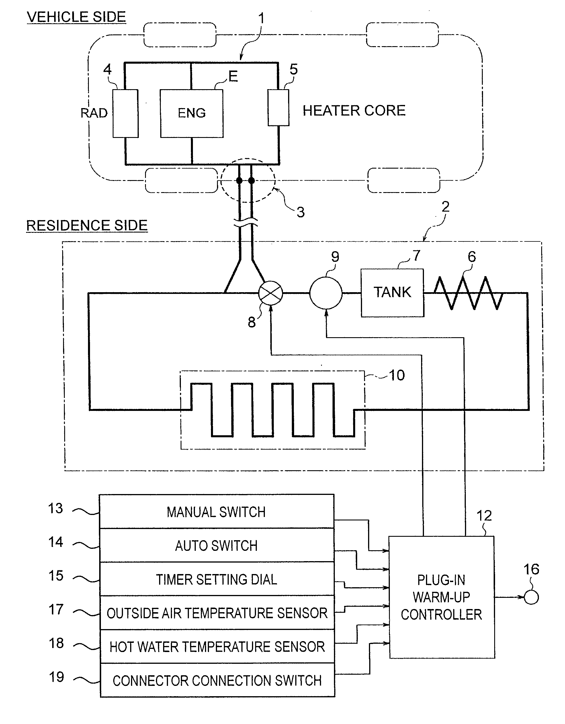
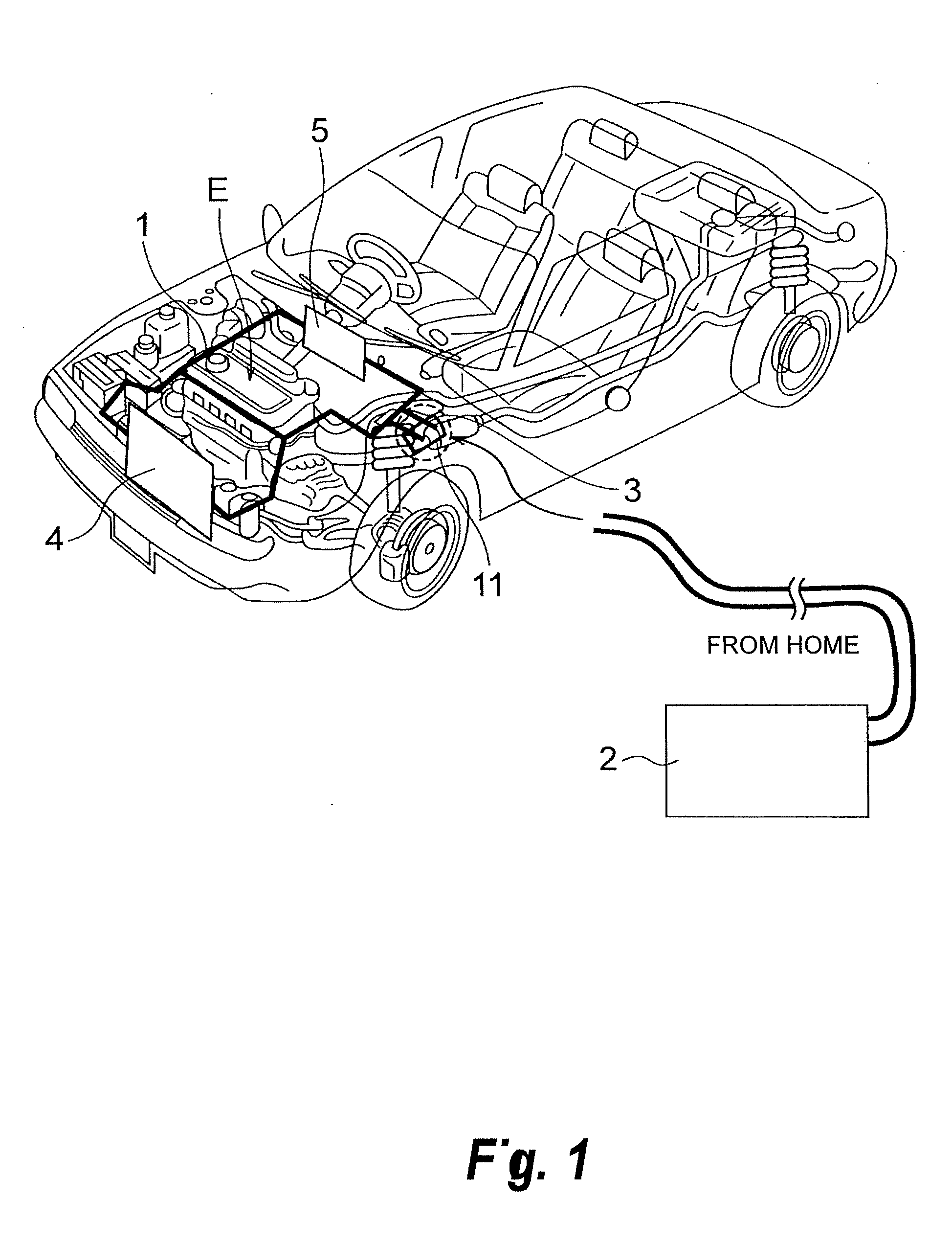
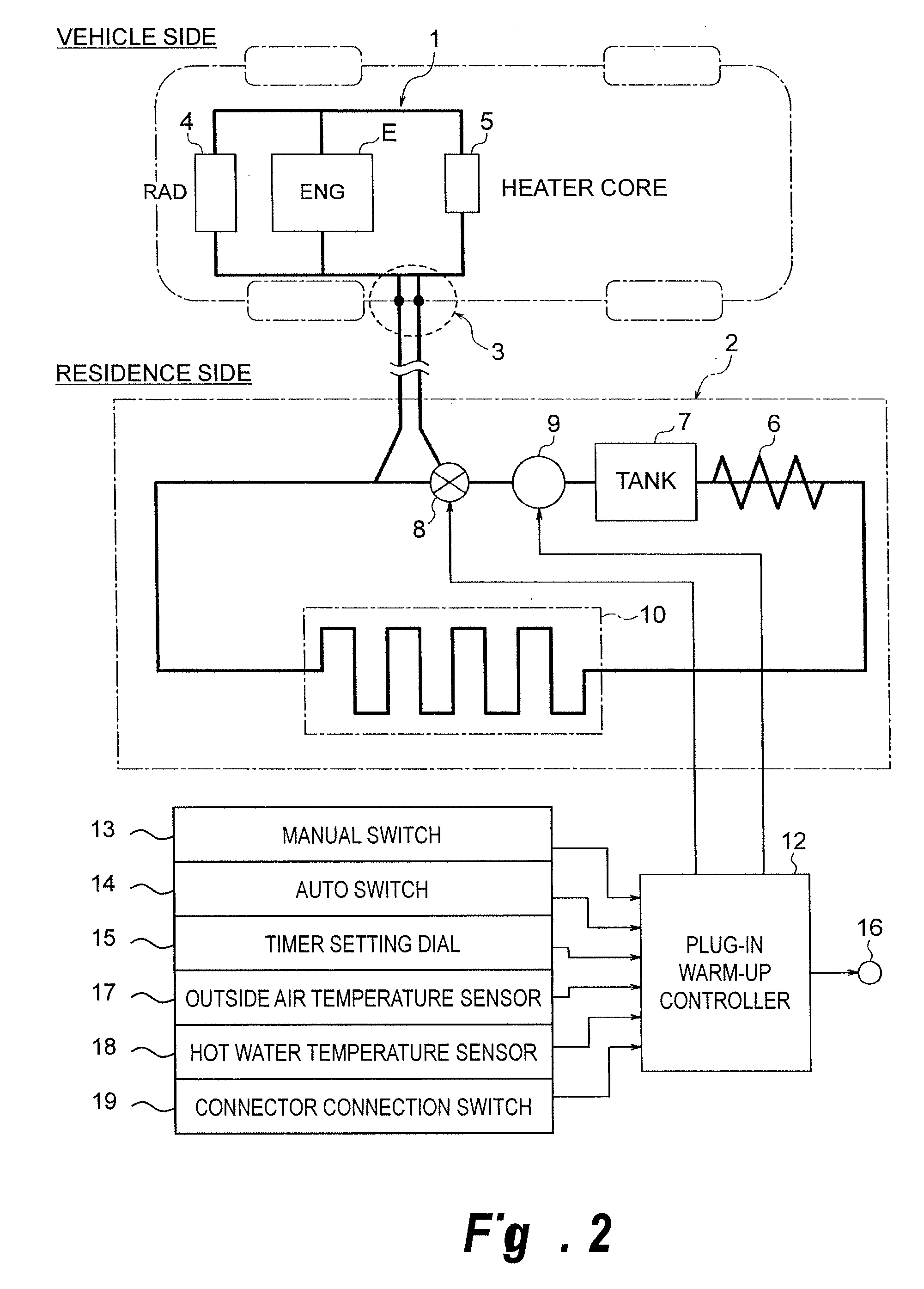
[0037]First, the constitution of this embodiment will be described. FIG. 1 is a perspective view showing an engine vehicle to which a warm-up system and a warm-up method for an engine (serving as an example of an in-vehicle power train) according to the first embodiment are applied. FIG. 2 is an illustrative view showing the engine warm-up system according to the first embodiment. FIG. 3 is a sectional view showing a state in which a connector of the engine warm-up system according to the first embodiment is disconnected immediately prior to connection. FIG. 4 is a sectional view showing a state in which the connector of the engine warm-up system according to the first embodiment is connected.

[0038]As shown in FIG. 1, the engine warm-up system according to the first embodiment pre-warms up of an engine E by transferring heat from a heat source to an engine cooling water circulation circuit 1 (vehicle side warm-up circuit) of the vehicle. A residential hot water circuit 2 (heat sourc...

second embodiment

[0096]In consideration of the use of household thermal energy to pre-warm up, the second embodiment is an example in which the temperature of the engine cooling water is raised via a heat exchanger, rather than circulating household hot water directly to the vehicle as in the first embodiment.

[0097]First, the constitution of the second embodiment will be described. FIG. 6 is an illustrative view of a warm-up system for an engine (serving as an example of an in-vehicle power train) according to the second embodiment.

[0098]As shown in FIG. 6, the engine warm-up system according to the second embodiment pre-warms up of an engine E by transferring heat from a heat source to an engine cooling water circulation circuit 1 (vehicle side warm-up circuit) of the vehicle. A residential hot water circuit 2 (heat source circuit) using a household heat source is provided as the heat source. The engine cooling water circulation circuit 1 and the residential hot water circuit 2 include a one-touch ...

third embodiment

[0107]Similarly to the second embodiment, the third embodiment is an example in which the temperature of the engine cooling water is raised via a heat exchanger, but here, the engine cooling water is warmed using household waste heat from a hot water supply, a bath, and so on instead of the floor heating heat source.

[0108]First, the constitution of this embodiment will be described. FIG. 7 is an illustrative view of a warm-up system for an engine (serving as an example of an in-vehicle power train) according to the third embodiment.

[0109]As shown in FIG. 7, the engine warm-up system according to the third embodiment pre-warms up of an engine E by transferring heat from a heat source to an engine cooling water circulation circuit 1 (vehicle side warm-up circuit) of the vehicle. A residential hot water circuit 2 (heat source circuit) using a household heat source is provided as the heat source. The engine cooling water circulation circuit 1 and the residential hot water circuit 2 incl...


PUM


Abstract

In a warm-up system that pre-warms up of an engine (E) by transferring heat from a heat source to an engine cooling water circulation circuit (1) of a vehicle, a residential hot water circuit (2) that uses a household heat source is provided as the heat source, and a one-touch connector (3) is provided in the engine cooling water circulation circuit (1) and the residential hot water circuit (2). The one-touch connector (3) connects the two circuits (1, 2) prior to start-up of the engine (E) such that heat is transferred to the engine cooling water circulation circuit (1), and disconnects the two circuits (1, 2) following heat transfer in preparation for start-up of the engine (E).

Description

FIELD OF INVENTION[0001]This invention relates to a warm-up system and a warm-up method that pre-warm up of an in-vehicle power train such as an engine, a transmission, or a motor by transferring heat from a heat source to a vehicle side warm-up circuit.DESCRIPTION OF THE RELATED ART[0002]A hybrid vehicle having an environment-responsive power train, demand for which is expected to increase in the coming years, discharges a smaller amount of heat than a vehicle having a conventional engine. During cold periods, therefore, the internal temperature of the vehicle cabin remains low for a while after the vehicle has begun to advance, and hence the heating performance of this type of hybrid vehicle is deficient.[0003]Further, pre-warming up of the engine and transmission is equally as important in terms of achieving an improvement in fuel economy as enhancing the fuel economy performance of the engine itself. An operating method for a power-generating internal combustion engine of a hybr...

Claims


Application Information

Patent Timeline
Patent Type & Authority Applications(United States)
IPC IPC(8): F02N17/06B60H1/22F02N19/10
CPCB60H1/00314F01P11/20F01P2037/02F24H9/122F24D15/00F24H1/009F02N19/10F24H9/13
Inventor KAMIYAMA, NAOHISANAKAJIMA, SHIROTAMAGAWA, SATOSHIHORI, RYOICHI
Owner CALSONIC KANSEI CORP
Why Eureka
Try Eureka