Direct metering fuel system with an integral redundant motor pump

a fuel system and motor technology, applied in the direction of positive displacement liquid engine, pump, lighting and heating apparatus, etc., can solve the problems of increasing system complexity and cost, affecting the overall system weight and complexity, and suffering certain drawbacks

Active Publication Date: 2009-03-19
HONEYWELL INT INC
View PDF12 Cites 20 Cited by
  • Summary
  • Abstract
  • Description
  • Claims
  • Application Information

AI Technical Summary

Benefits of technology

[0005]In one embodiment, and by way of example only, a direct metering fuel supply system includes a plurality of axial gap motors, a fixed displacement, variable speed positive displacement piston pump, and a gas turbine engine control. Each axial gap motor is configured to be selectively energized and is operable, upon being energized, to supply a drive torque at a drive speed. The fixed displacement, variable speed positive displacement piston pump is coupled to each of the axial gap motors to receive the drive torque selectively supplied therefrom and is operable, upon receipt of the drive torque, to supply fuel at a flow rate dependent on the drive speed. The gas turbine engine control is adapted to receive fuel flow commands and is operable, in response to the fuel flow commands, to energize one of the plurality of axial gap motors.
[0006]In another exemplary embodiment, a direct metering fuel supply system includes a pump housing, a plurality of axial gap motors, a fixed displacement, variable speed positive displacement piston pump, and a gas turbine engine control. Each axial gap motor is disposed within the pump housing and is configured to be selectively energized and is operable, upon being energized, to supply a drive torque at a drive speed. The fixed displacement, variable speed positive displacement piston pump is disposed within the pump housing, is coupled to each of the axial gap motors to receive the drive torque selectively supplied therefrom and is operable, upon receipt of the drive torque, to supply fuel at a flow rate dependent on the drive speed. The gas turbine engine control is adapted to receive fuel flow commands and is operable, in response to the fuel flow commands, to energize one of the plurality of axial gap motors. Each axial gap motor includes a pair of permanent magnet rotors and a stator. Each permanent magnet rotors is coupled to the fixed displacement, variable speed positive displacement piston pump and has a plurality of magnetic dipoles disposed thereon. The stator has a plurality of independent stator coils disposed thereon, and is disposed between, and spaced axially apart from, each of the rotors.
[0007]In yet another exemplary embodiment, a direct metering fuel supply system includes a plurality of axial gap motors, a fixed displacement, variable speed positive displacement piston pump, and a gas turbine engine control. Each axial gap motor is configured to be selectively energized and is operable, upon being energized, to supply a drive torque at a drive speed. The fixed displacement, variable speed positive displacement piston pump is coupled to each of the axial gap motors to receive the drive torque selectively supplied therefrom and is operable, upon receipt of the drive torque, to supply fuel at a flow rate dependent on the drive speed. The gas turbine engine control is adapted to receive fuel flow commands and is operable, in response to the fuel flow commands, to energize one of the plurality of axial gap motors, and is further operable to determine operability of the energized axial gap motor and, based on this determination, to selectively deenergize the energized axial gap motor and energize a deenergized axial gap motor. Each axial gap motor includes a pair of permanent magnet rotors and a stator. Each permanent magnet rotors is coupled to the fixed displacement, variable speed positive displacement piston pump and has a plurality of magnetic dipoles disposed thereon. The stator has a plurality of independent stator coils disposed thereon, and is disposed between, and spaced axially apart from, each of the rotors.

Problems solved by technology

Nonetheless, it can suffer certain drawbacks.
For example, the metering valve and bypass valve can add to overall system weight and complexity.
Moreover, control of the metering valve and bypass valve can result in increased system complexity and cost.
Yet, efforts to implement direct fuel metering control systems have also been impeded by certain drawbacks.
Thus, actuator operation can cause a droop in the fuel supplied to the engine, and thus an undesirable engine speed droop.
It is also postulated that such fuel supply variations to the engine could yield unpredictable, and potentially less controllable, engine transients.
Moreover, many current direct metering fuel systems are not as thermally efficient and cost effective as desired, and some systems may not exhibit sufficient redundancy and / or reliability.

Method used


Image

  • Direct metering fuel system with an integral redundant motor pump
  • Direct metering fuel system with an integral redundant motor pump
  • Direct metering fuel system with an integral redundant motor pump

Examples


Embodiment Construction

[0012]The following detailed description of the invention is merely exemplary in nature and is not intended to limit the invention or the application and uses of the invention. Furthermore, there is no intention to be bound by any theory presented in the preceding background of the invention or the following detailed description of the invention. In this regard, although an embodiment of the invention is described as being implemented in an aircraft, it will be appreciated that the invention may be implemented in numerous and varied end-use environments where fuel flow to a gas turbine engine is controlled.

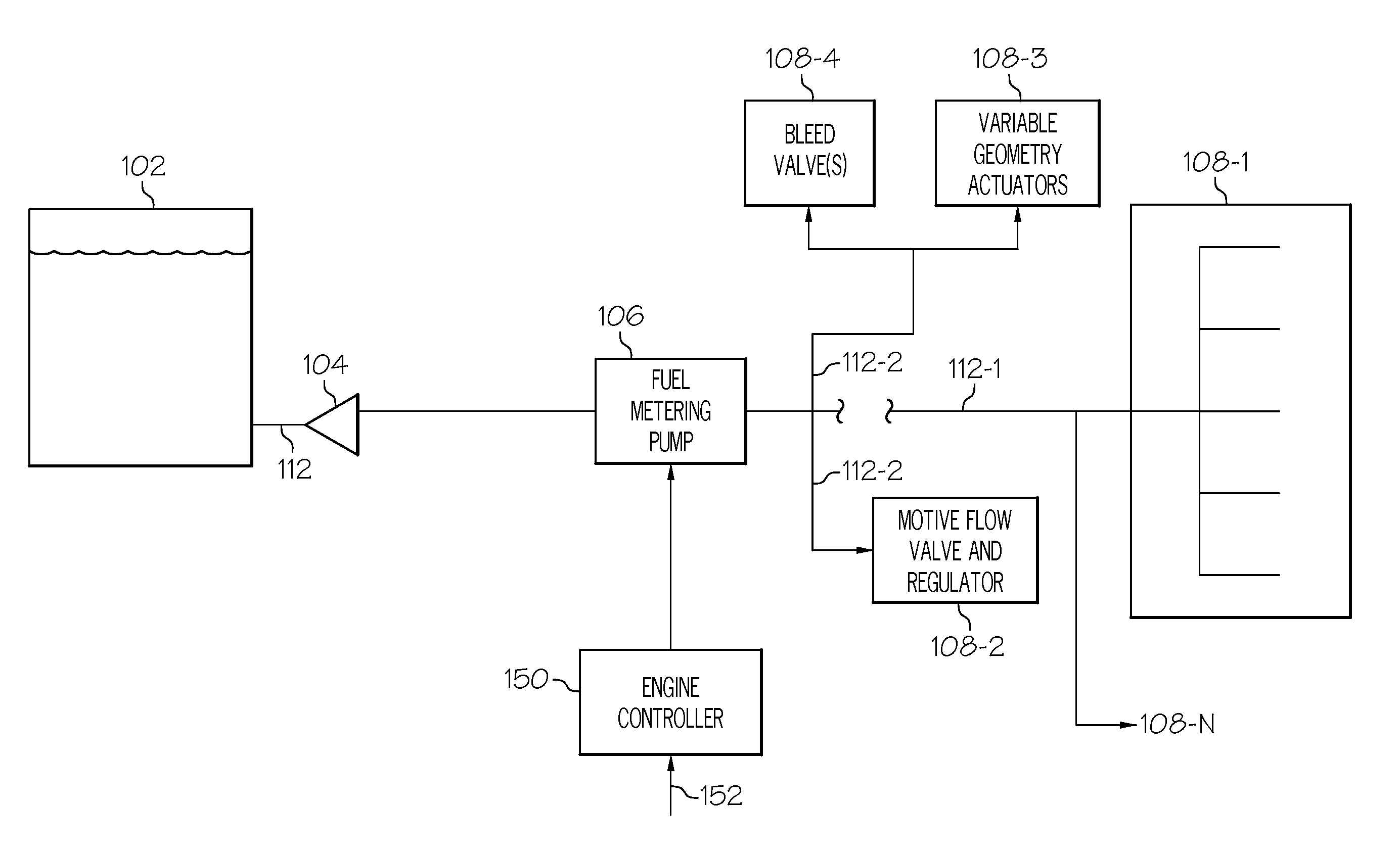
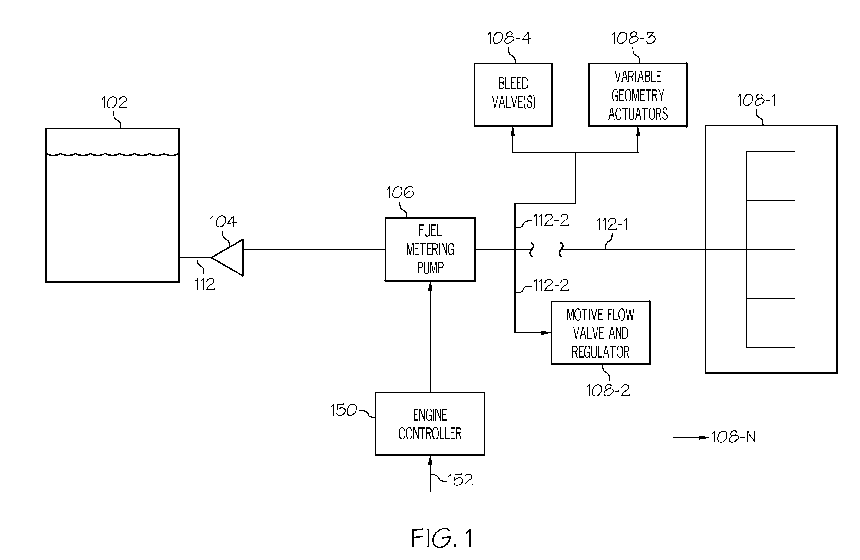
[0013]A simplified schematic diagram of one embodiment of a direct metering fuel control system for a gas turbine engine, such as a turbofan jet aircraft engine, is depicted in FIG. 1. The system 100 includes a fuel source 102, one or more pumps 104, 106, and an engine control 150. The fuel source 102, which is preferably implemented as one or more tanks, stores fuel that is to be...


PUM


Abstract

A direct metering fuel supply system includes a plurality of axial gap motors, a fixed displacement, variable speed positive displacement piston pump, and a gas turbine engine control. Each axial gap motor is configured to be selectively energized and is operable, upon being energized, to supply a drive torque at a drive speed. The fixed displacement, variable speed positive displacement piston pump is coupled to each of the axial gap motors to receive the drive torque selectively supplied therefrom and is operable, upon receipt of the drive torque, to supply fuel at a flow rate dependent on the drive speed. The gas turbine engine control is adapted to receive fuel flow commands and is operable, in response to the fuel flow commands, to energize one of the plurality of axial gap motors.

Description

TECHNICAL FIELD[0001]The present invention generally relates to fuel metering systems and, more particularly, to direct metering fuel systems with integral redundant pump motors.BACKGROUND[0002]Many gas turbine engine fuel supply systems include a fuel source, such as a fuel tank, and one or more pumps that draw fuel from the fuel source and deliver pressurized fuel to the fuel manifolds in the engine combustor via a main supply line. The main supply line may include one or more valves in flow series between the pumps and the fuel manifolds. These valves generally include, for example, a main metering valve and a pressurizing-and-shutoff valve downstream of the main metering valve. In addition to the main supply line, many fuel supply systems also include a bypass flow line connected upstream of the metering valve that bypasses a portion of the fuel flowing in the main supply line back to the inlet of the one or more pumps, via a bypass valve. The position of the bypass valve is typ...

Claims


Application Information

Patent Timeline
Patent Type & Authority Applications(United States)
IPC IPC(8): F02M57/02
CPCF02C7/20F23K2301/206F23K5/04F02C9/26F23K2300/206
Inventor EMO, STEPHEN M.PORTOLESE, LARRY A.
Owner HONEYWELL INT INC
Why Eureka
Try Eureka