
Self-regulated thermal energy system

Inactive Publication Date: 2009-03-19
SEIDEL PESSACH
View PDF7 Cites 4 Cited by
  • Summary
  • Abstract
  • Description
  • Claims
  • Application Information

AI Technical Summary

Benefits of technology

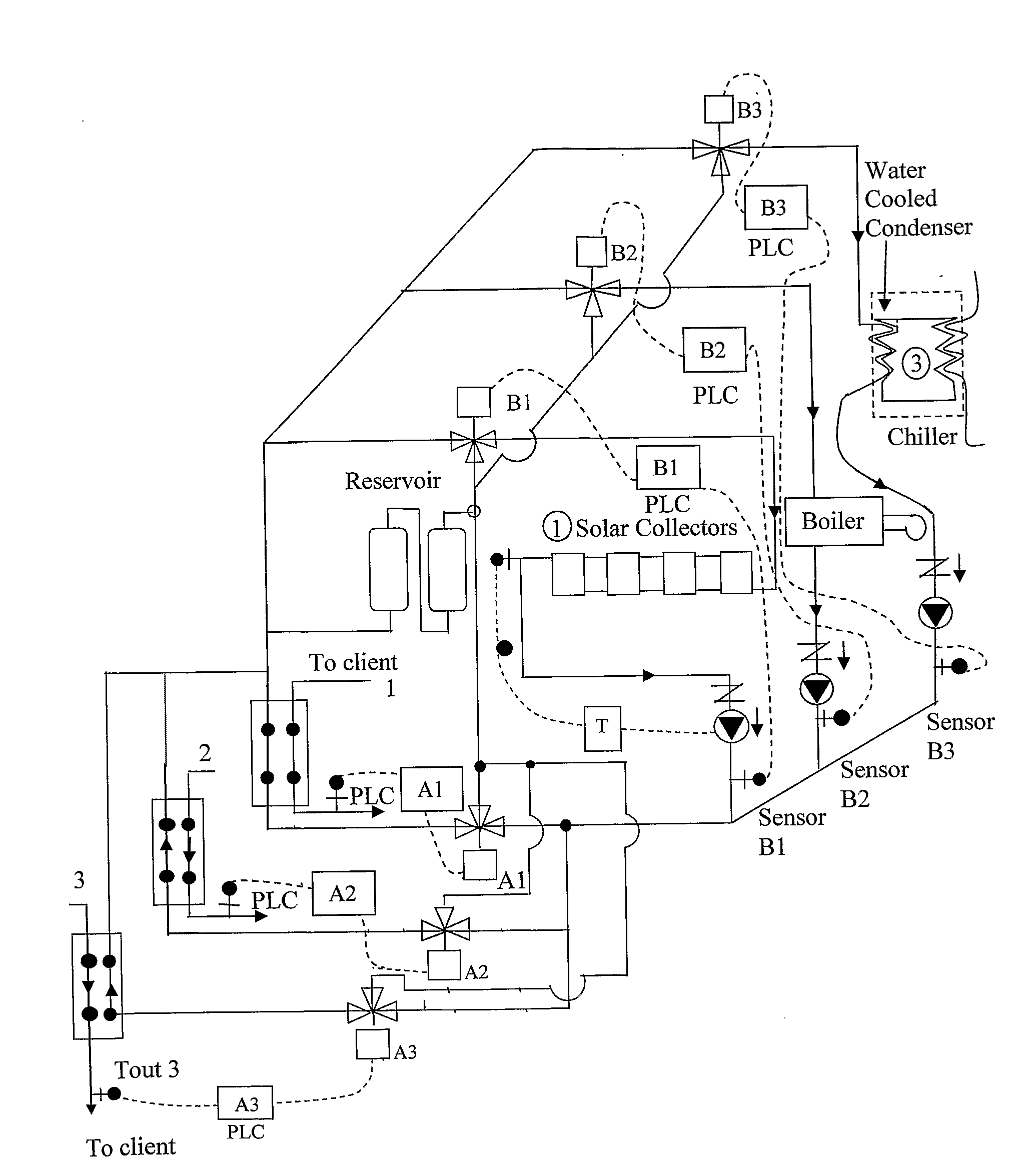
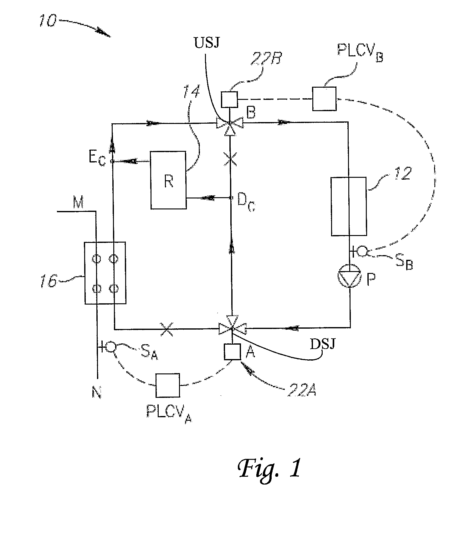
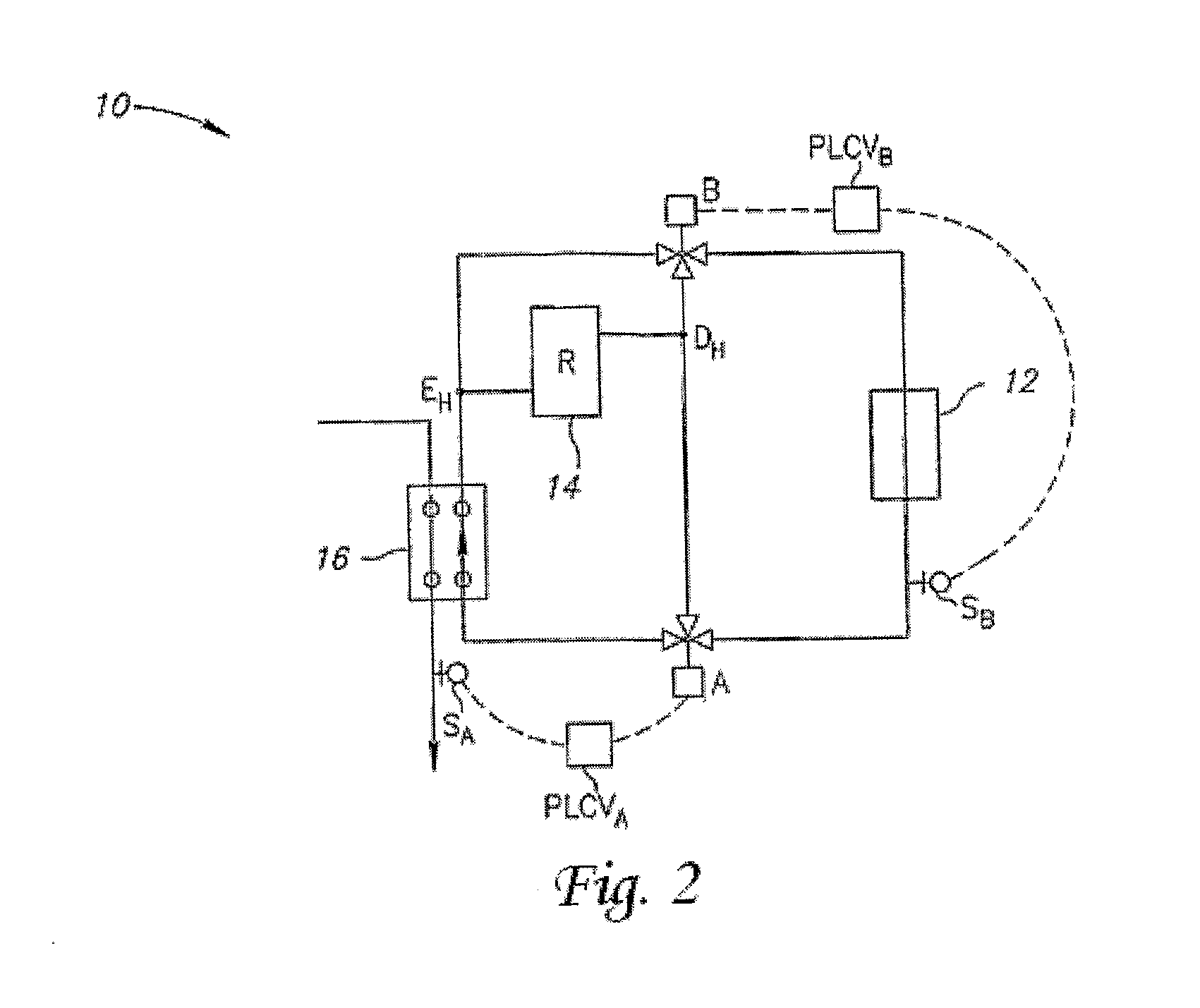
[0004]It is an aim of the present invention to provide a self-regulating thermal energy storage system (10) for use in conjunction with at least one thermal energy client (16), which comprising: (I) at least one thermal energy generation source (12) for imparting to at least one thermal energy carrier fluid a predetermined temperature change; (II) said at least one thermal energy client (16) is communicated in series, parallel or a combination thereof to said generator (12); (III) at least one thermal energy storage reservoir (14), adapted to store thermal energy generated by said generator (12) at the time that the said client (16) does not fully utilize said energy, communicated in parallel to a bypass of said storage and in series, parallel or a combination thereof to said generator (12) and said client (16); (IV) a first and a second fluid flow directors configured so that said first director (22A) is located in an upstream junction (USJ) communicating said generator (12), client (16) and reservoir (14); said first director (22A) functions to direct the flow of said fluid from the generator (12) in at least one of two directions, namely towards said client (16) and/or towards said reservoir (14); said second director (22B) is located in a downstream junction (DSJ) communicating said generator (12), client (16) and reservoir (14), said second director (22B) functions to direct the flow of said fluid towards the generator (12) in at least one of two directions, namely from said client (16) and/or from the reservoir (14), being interconnected with the DSJ-USJ supply line, via Dc or Dh, wherein Dc or Dh is a junction communicating said reservoir (14) and said DSJ-USJ supply line junction; wherein the thermal energy consumption of said client (16) equals the thermal energy generation capacity of said generator (12), said fluid is circled directly from said generator (12) to said client (16) via said USJ, and vice versa, from said client (16) to said generator (12) via said DSJ; and, wherein the momentary thermal energy requirements of said client (16) is lower than the thermal energy generation capacity of said generator (12), only a portion of said fluid is circled from said generator (12) to said client (16) via said USJ, and the remaining portion is supplied by said first director (22A) towards said reservoir (14), in case said generator (12) is adapted to cool said client (16) (a cooling system), a cold fluid is supplied to said lower portion of said reservoir (14) thereby to cause a release of heat from the relatively warm layers of said storage medium in said upper portion thereof, yet in case said generator (12) is adapted to heat said client (16) (a heating system), a worm fluid is supplied to said higher portion of said reservoir (14) thereby to cause a release of cold fluid from the relatively cold layers of said storage medium in said l

Problems solved by technology

In more complicated cases however, the thermal requirements of the client are not steady, e.g., the client's thermal requirements are temporarily lower than the generator's and solids tend to be distributed generally vertically, with warmer layers being positioned above cooler lower layers.

Method used


Image

  • Self-regulated thermal energy system
  • Self-regulated thermal energy system
  • Self-regulated thermal energy system

Examples


Embodiment Construction

[0019]The following description is provided, alongside all chapters of the present invention, so as to enable any person skilled in the art to make use of said invention and sets forth the best modes contemplated by the inventor of carrying out this invention. Various modifications, however, will remain apparent to those skilled in the art, since the generic principles of the present invention have been defined specifically to provide self-regulating thermal energy storage system and self-regulating method.

[0020]The term ‘Energy generation source’ or ‘generator’ refers hereinafter to any source of heat and / or cold. For example, it may be an electric or diesel powered boiler, a solar powered system, a geothermal system or the like; a chiller, or cold river or sea water or the like etc.

[0021]The term ‘Energy client’ or ‘client’ refers hereinafter to any ‘beneficiary’ of the stored energy to which energy (heat or cold) generated in the energy generation source is provided. The client c...


PUM


Abstract

The aim of the present invention is to provide a self-regulating thermal energy storage system for use in conjunction with at least one thermal energy client. The invention also discloses methods for self-regulating, the storage, and use of thermal energy in thermal energy storage system, as well as a consul for system as defined above. This consul is modulated, unitary, integrated or stands alone as a control system adapted for controlling the heated / cooled system defined above.

Description

FIELD OF THE INVENTION[0001]The present invention relates to self-regulated thermal energy system, methods and consuls thereof.BACKGROUND OF THE INVENTION[0002]Various approaches were taken in the art to generate thermal energy, wherein this energy is being either the presence of heat, as provided by a heating system, boiler, heat exchanger or the like, or the presence of cold, as provided by a cooling system, chiller, heat exchanger, or the like. In a simplified manner, a heat exchange system comprises two reciprocal steps: after a first thermal energy exchange, thermal energy carrier fluid is recycled from a thermal energy generator to a client, whereat a second (and opposite) thermal energy exchange is provided and vice versa.[0003]More specifically, and as utilized in many industrial systems, the thermal energy is generated by one or more thermal energy generation sources and supplied in a predetermined capacity to at least one thermal energy client by a means of a conduit syste...

Claims


Application Information

Patent Timeline
IPC IPC(8): F28D5/00
CPCF24D3/08F24D3/1066F24D11/0221Y02E60/142Y02B10/20Y02B10/70Y02B30/126F28D20/0034Y02A30/60Y02E60/14
Inventor SEIDEL, PESSACH
Owner SEIDEL PESSACH
Learn More