Sustainable torque system

a technology of sustainable torque and torque system, which is applied in the direction of mechanical equipment, dc/dc converter, transportation and packaging, etc., can solve the problems of high cost, high cost, and inability to provide a sustainable torque system, and achieves the effect of reducing and increasing the cost of refueling

Inactive Publication Date: 2016-09-29
ROSS BENNETT
View PDF1 Cites 0 Cited by
  • Summary
  • Abstract
  • Description
  • Claims
  • Application Information

AI Technical Summary

Benefits of technology

[0022]Another thought is to provide a sustainable torque system that does not utilize a combustible engine.
[0023]An additional thought is to a provide a sustainable torque system that does not utilize a plurality of battery as the main and constant power source for energy.
[0024]A further thought is to provide a sustainable torque system that does not utilize conventional fueling procedures of a combustible engine vehicle.
[0025]Another thought is to provide a sustainable torque system that does not utilize a conventional plug in charging system to recharge a depleted battery system that is used as the primary energy source to power a conventional electric car.

Problems solved by technology

Combustible engines have constant and costly refueling, and are costly.
There are also many controversial environmental concerns associated with fuel burning engines, ranging from global warming, toxic rain, excessive carbon emissions, air pollution, to name a few.
Large costs are associated with each of the afore-mentioned power sources ranging from: land purchases, endeavors to extract natural resources from land or off shore, construction costs of energy farms (wind turbine or solar) and construction costs associated with dam building.
While these devises may be suitable for the particular purpose to which they address, they are not suitable for providing a sustainable torque system that does not consist of a combustible engine, a battery stack as the continued source for powering a vehicle, a combustible engine with a generator mounted to it creating electric power, lengthy recharging time of primary battery source.
Items such as batteries, hydrogen fuel cells, solar panels, combustible engines, generators, etc., alone or in combination are used to extend the range of travel for combustible, electric or hybrid vehicles, while resulting in one of the following: costly refueling, timely recharging process, dependence on sun light, wave activity or wind available, costly infrastructure deployment.

Method used


Image

  • Sustainable torque system
  • Sustainable torque system
  • Sustainable torque system

Examples


second embodiment

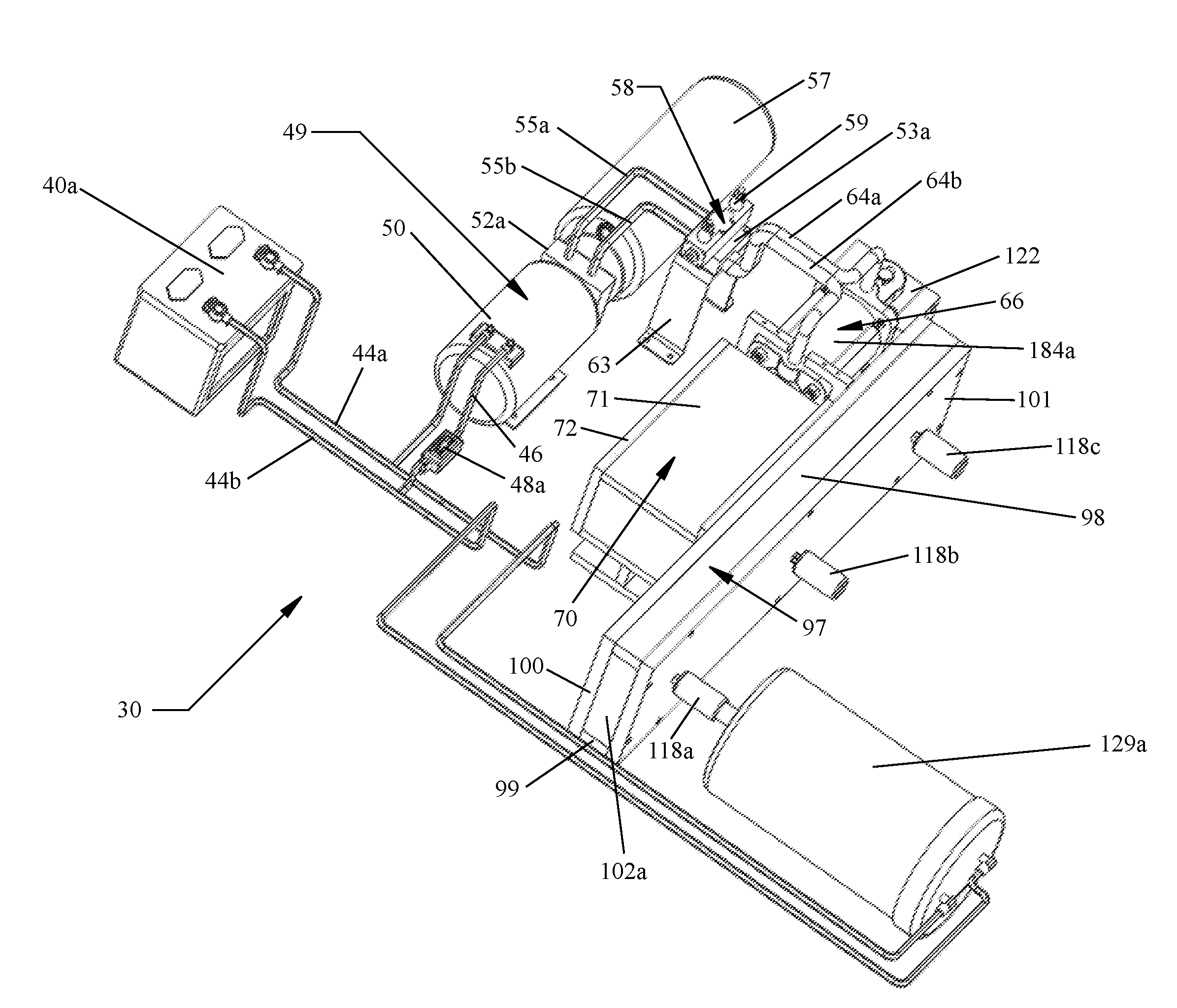
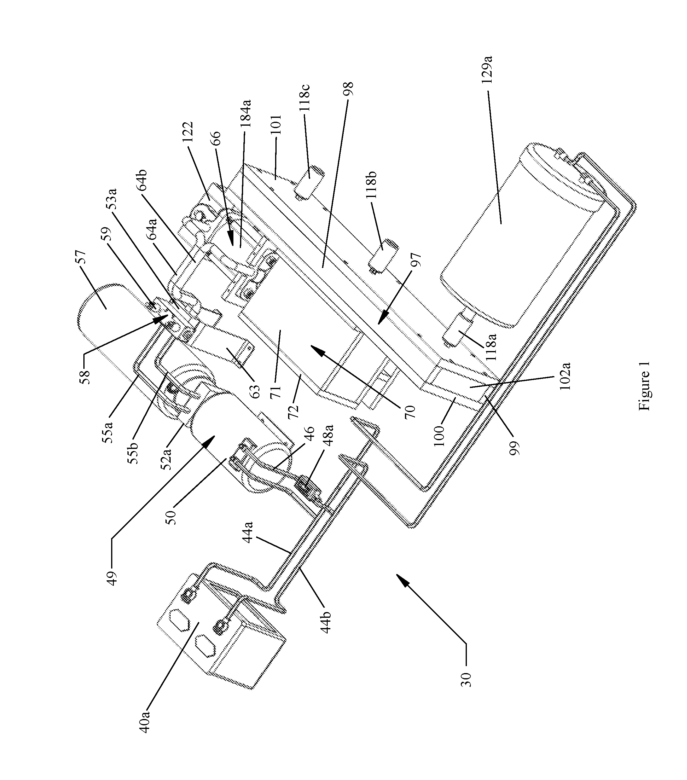
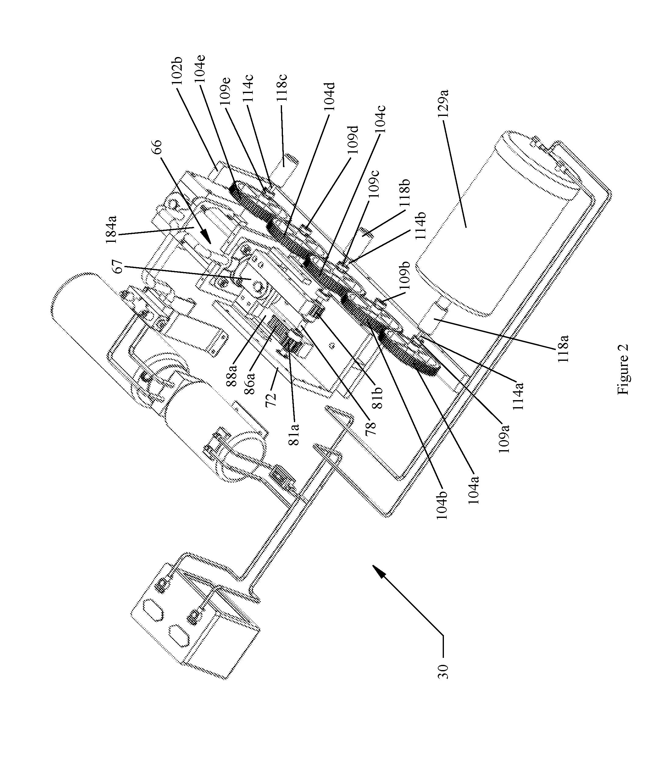
[0053]Turning now descriptively to the drawings, in which similar reference characters denote similar elements throughout the several views, FIGS. 9, through 12 illustrate a sustainable torque system-2156, which comprises a power source, battery assembly 41, connected by conductive wires 160a and 160b to inverter / converter 164, which is connected to ac wire 168a, which connects to control box-1176. Control box-1176 connects to ac wire 168c which connects to hydraulic pump assembly ac 180. Hydraulic pump assembly ac 180 connects to flow tubings 55a and 55b, which connects to auto reciprocating valve assembly 58, which connects to flow tubing long 182a and 182b, which connects to multiple cylinder assembly 183. Multiple cylinder assembly 183 connects mechanically to linear to rotational box 70, which connects mechanically to rotary transmission assembly 188, which connects mechanically to transfer assembly 97, which connects mechanically to shaft sleeve lock 118a, which connects mecha...

third embodiment

[0055]Turning now descriptively to the drawings, in which similar reference characters denote similar elements throughout the several views, FIGS. 9, 13 through 16 illustrate a sustainable torque system-3204, which comprises a power source, battery assembly 41, connected by conductive wires 160a and 160b to inverter / converter 164, which is connected to ac wire 168a, which connects to control box-2177. Control box-2177 connects to ac wire 208, which connects to hydraulic pump / cylinder assembly 205, control box-2177 also connects to directional valve power supply wire 206. Hydraulic pump / cylinder assembly 205 connects mechanically to rotary transmission assembly 188, which connects mechanically to transfer assembly 97, which connects mechanically to shaft sleeve lock 118a, which connects to ac generator 150c. Ac generator 150c connects to ac wire 168b, which connects to control box-2177. Rotate lever on control box-2177 to generator setting. Energy from ac generator 150c powers sustai...

fourth embodiment

[0057]Turning now descriptively to the drawings, in which similar reference characters denote similar elements throughout the several views, FIGS. 9, 17 through 20 illustrate a sustainable torque system-4255. A polarity of reference numbers from FIGS. 10 and 11, sustainable torque system-2156, are applicable to describe items within sustainable torque system-4255. Sustainable torque system-4255 differs with the use of pneumatic pump assembly ac 258. Pneumatic pump assembly ac 258 connects to outlet flow tubing 285 which connects to auto reciprocating pneumatic assembly 275. Additional connections are referenced in FIG. 10.

[0058]As shown in FIGS. 9, 17 through 20 of the drawings representing sustainable torque system-4255, many of the items in this embodiment have been discussed, described and illustrated in previous embodiments. Sustainable torque system-4255 uses a pneumatic pump assembly ac 258. Pneumatic pump assembly ac 258 comprised of pump ac motor 259, comprised of well-known...


PUM


Abstract

A sustainable torque system for providing torque or energy without the need of a combustible engine, or batteries as a continuing/ongoing energy source. The sustainable torque system may be used to propel or to drive a generator for power, or a combination of both, but not limited to the afore-mentioned. One embodiment consists of an initial power source that is connected by conductive material to an electric motor hydraulic pump system which connects via tubing to a directional flow valve which connects via tubing to a cylinder. The cylinder is connected mechanically to a rotary transmission which converts the linear strokes of the cylinder into rotational energy. A generator is connected mechanically to the rotary transmission in which the generator creates power. The generator is connected by conductive material back to the electric motor hydraulic pump system. The initial power source may now be disengaged, as the sustainable torque system is running on power from the generator.

Description

CROSS-REFERENCE TO RELATED APPLICATIONS[0001]None.FEDERALLY SPONSORED RESEARCH[0002]None.SEQUENCE LISTING[0003]NoneFIELD OF CLASSIFICATION SEARCH[0004]180 / 65.21, 180 / 165, 305, 307, 308REFERENCES CITED[0005]U.S. Pat. No. 8,162,094 B2 4 / 2012 Gary Ser. No. 13 / 155,283U.S. CLASSIFICATION[0006]180 / 65.2; 180 / 656; 180 / 165; 60 / 718; 475 / 2; 475 / 5180 / 243, 105 / 50, 180 / 60, 180 / 65.29, 903 / 904, 136 / 291, 180 / 65.285, 903 / 907, 180 / 65.21, 903 / 916, 180 / 65.225, 903 / 903, 318 / 139INTERNATIONAL CLASSIFICATION[0007]B60K8 / 00, B60K23 / 08, B60W10 / 26, B60K17 / 356, B60K6 / 28, B60L8 / 00, B60K6 / 52, B60K17 / 04, B60K16 / 00, B60W10 / 08, B60K6 / 48, B60W20 / 00, B60L11 / 18, B60L11 / 12BACKGROUND[0008]1. Field of the Embodiment[0009]This relates to a sustainable torque system capable of generating torque that may be used to generate electricity for a wide range of industries including but limited to: the transportation industry (for example, automobiles, buses, trucks, rail, etc.) residential homes, commercial buildings, industrial pl...

Claims


Application Information

Patent Timeline
Patent Type & Authority Applications(United States)
IPC IPC(8): H02K47/14B60L11/18B60L11/00
CPCH02K47/14B60L11/002H02K53/00B60L2270/10Y10S74/09B60L11/1811B60L50/90Y02T10/64
Inventor ROSS, BENNETT
Owner ROSS BENNETT
Why Eureka
Try Eureka