Eureka AIR delivers breakthrough ideas for toughest innovation challenges, trusted by R&D personnel around the world.

Method and apparatus for optimized dematching layer assembly in an ultrasound transducer

a dematching layer and ultrasound technology, applied in piezoelectric/electrostrictive transducers, generators/motors, instruments, etc., can solve the problems of transducer use, severe limit the mechanical action of the dematching layer, and vibration from the back of the acoustical stack

Active Publication Date: 2009-03-19
GENERAL ELECTRIC CO
View PDF10 Cites 21 Cited by
  • Summary
  • Abstract
  • Description
  • Claims
  • Application Information

AI Technical Summary

Problems solved by technology

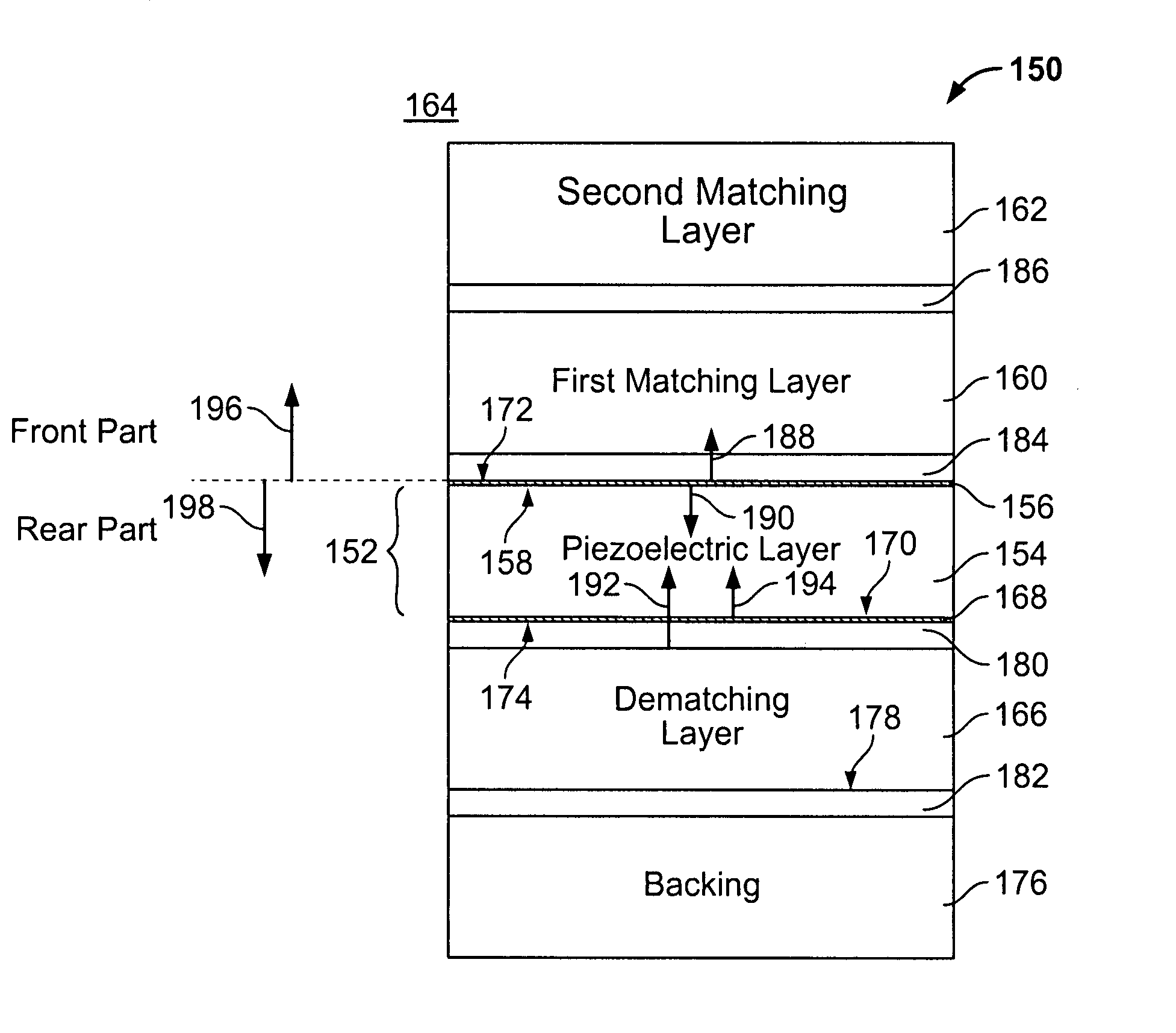
A known problem in ultrasound transducers using standard half wavelength thickness (λ / 2) ceramic piezoelectric materials within the acoustical stack is the perturbation from the back of the acoustical stack, such as radiation losses, parasitic reflections and the like.
Unfortunately, problems occur when the transducers are used at some frequencies.
For example, when the transducers are operating at frequencies above 5 MHz, the ceramic and dematching layer substrate properties and the joining material there-between together severely limit the mechanical action of the dematching layer.
However, it has been very difficult to ensure direct contact between the dematching and ceramic layers, leading to rejection of assembled materials due to unacceptable performance.

Method used


Image

  • Method and apparatus for optimized dematching layer assembly in an ultrasound transducer
  • Method and apparatus for optimized dematching layer assembly in an ultrasound transducer
  • Method and apparatus for optimized dematching layer assembly in an ultrasound transducer

Examples


Embodiment Construction

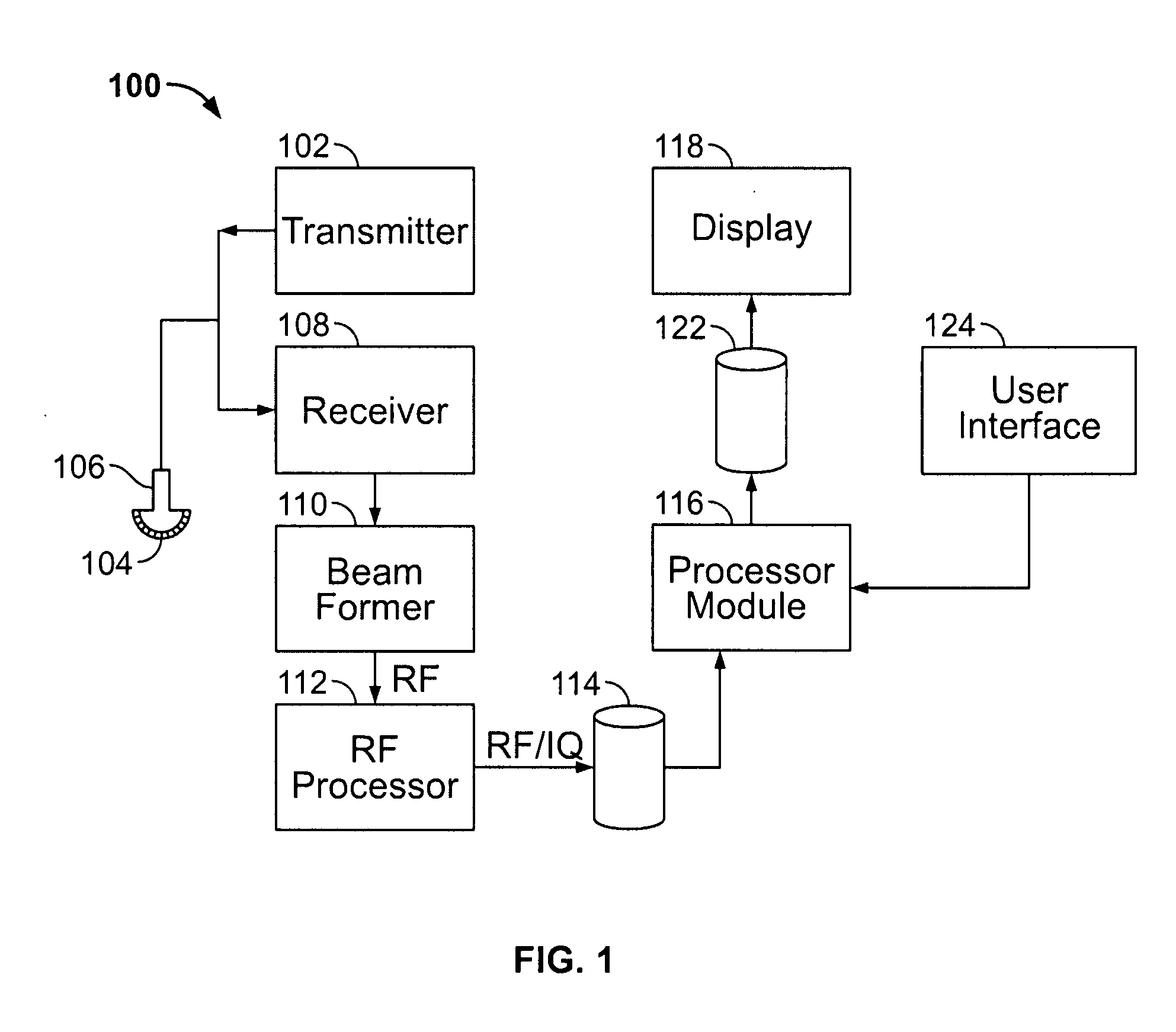
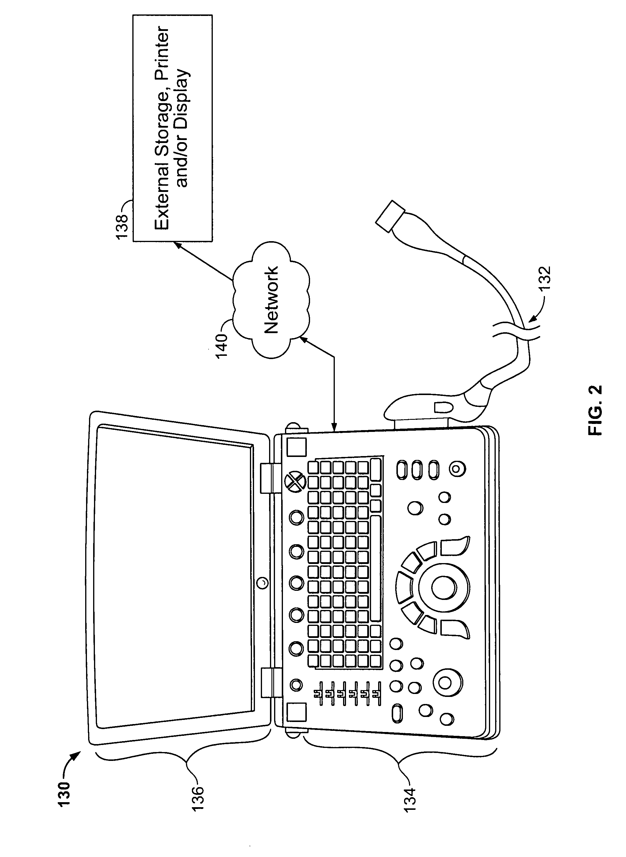
[0024]The foregoing summary, as well as the following detailed description of certain embodiments of the present invention, will be better understood when read in conjunction with the appended drawings. To the extent that the figures illustrate diagrams of the functional blocks of various embodiments, the functional blocks are not necessarily indicative of the division between hardware circuitry. Thus, for example, one or more of the functional blocks (e.g., processors or memories) may be implemented in a single piece of hardware (e.g., a general purpose signal processor or random access memory, hard disk, or the like). Similarly, the programs may be stand alone programs, may be incorporated as subroutines in an operating system, may be functions in an installed software package, and the like. It should be understood that the various embodiments are not limited to the arrangements and instrumentality shown in the drawings.

[0025]As used herein, an element or step recited in the singu...


PUM

PropertyMeasurementUnit
frequencyaaaaaaaaaa
operating frequencyaaaaaaaaaa
thicknessaaaaaaaaaa

Abstract

A method for manufacturing an acoustical stack for use within an ultrasound transducer comprises using a user defined center operating frequency of an ultrasound transducer that is at least about 2.9 MHz. A piezoelectric material and a dematching material are joined with an assembly material to form an acoustical connection therebetween. The piezoelectric material has a first acoustical impedance and *at least one of* an associated piezoelectric rugosity (Ra) and piezoelectric waviness (Wa). The dematching material has a second acoustical impedance that is different than the first acoustical impedance and at least one of an associated dematching Ra and dematching Wa. The piezoelectric and dematching materials have an impedance ratio of at least 2. The assembly material has a thickness that is based on the center operating frequency and at least one of the piezoelectric Ra, piezoelectric Wa, dematching Ra and dematching Wa.

Description

BACKGROUND OF THE INVENTION[0001]This invention relates generally to ultrasound transducers, and more particularly, to acoustical stacks that are within the ultrasound transducers.[0002]Ultrasound transducers (also commonly referred to as probes) typically have many acoustical stacks arranged in one dimension or in two-dimensional (2D) arrays. Each acoustical stack corresponds to an element within the transducer, and a transducer may have many acoustical stacks therein, such as several thousand arranged in the 2D array. A known problem in ultrasound transducers using standard half wavelength thickness (λ / 2) ceramic piezoelectric materials within the acoustical stack is the perturbation from the back of the acoustical stack, such as radiation losses, parasitic reflections and the like. To address this problem, a quarter wavelength thickness (λ / 4) piezoelectric material has been used and is coupled with a high impedance layer that is positioned at the rear-facing part of the piezoelec...

Claims


Application Information

Patent Timeline
Patent Type & Authority Applications(United States)
IPC IPC(8): H01L41/22H01L41/00H10N30/01
CPCG10K11/02Y10T29/49005Y10T29/42Y10T29/49004
Inventor GELLY, JEAN-FRANCOISMILLS, DAVID MARTINLANTERI, FREDERICBAUMGARTNER, CHARLES EDWARDCALISTI, SERGE GERARD
Owner GENERAL ELECTRIC CO
Why Eureka
Eureka Blog
Learn More