Eureka AIR delivers breakthrough ideas for toughest innovation challenges, trusted by R&D personnel around the world.

Signal generating apparatus and method thereof

Inactive Publication Date: 2009-03-19
MEDIATEK INC
View PDF20 Cites 19 Cited by
  • Summary
  • Abstract
  • Description
  • Claims
  • Application Information

AI Technical Summary

Benefits of technology

[0006]Therefore, one of the objectives of the present invention is to provide a phase-locked loop synthesizer with sub-band and loop gain calibration devices, and a method thereof.

Problems solved by technology

As the system speed rapidly increases, it is difficult to maintain the locking speed of the frequency locking circuit.
In fact, the locking speed of the frequency locking circuit is generally limited by the frequency of a reference clock signal.
Therefore, it is problematic to apply a traditional frequency locking circuit to a high speed hopping system with high reference clock signal frequency.

Method used


Image

  • Signal generating apparatus and method thereof
  • Signal generating apparatus and method thereof
  • Signal generating apparatus and method thereof

Examples


Embodiment Construction

[0017]Certain terms are used throughout the description and following claims to refer to particular components. As one skilled in the art will appreciate, electronic equipment manufacturers may refer to a component by different names. This document does not intend to distinguish between components that differ in name but not in function. In the following description and in the claims, the terms “include” and “comprise” are used in an open-ended fashion, and thus should be interpreted to mean “include, but not limited to . . . ”. Also, the term “couple” is intended to mean either an indirect or direct electrical connection. Accordingly, if one device is coupled to another device, that connection may be through a direct electrical connection, or through an indirect electrical connection via other devices and connections.

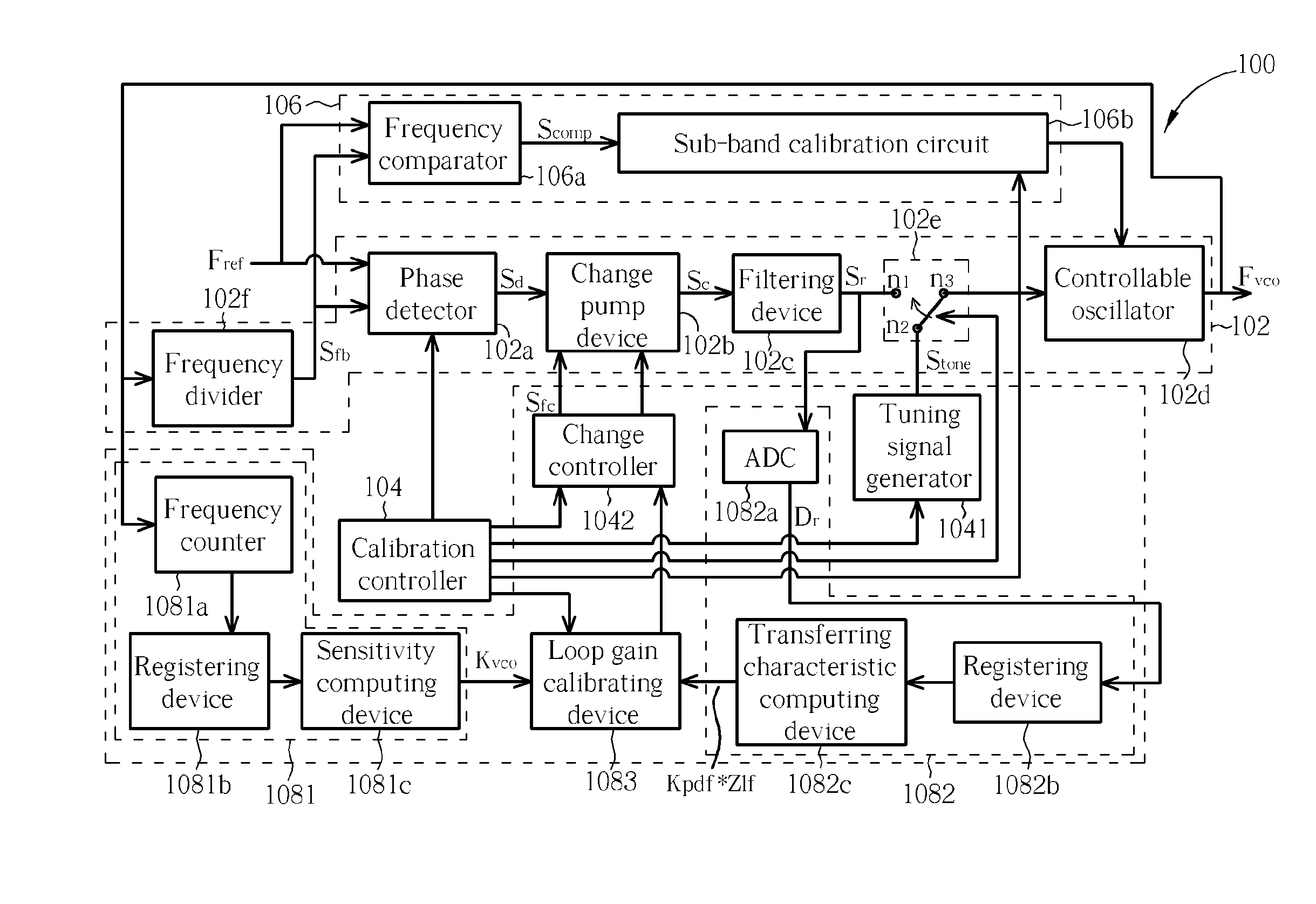
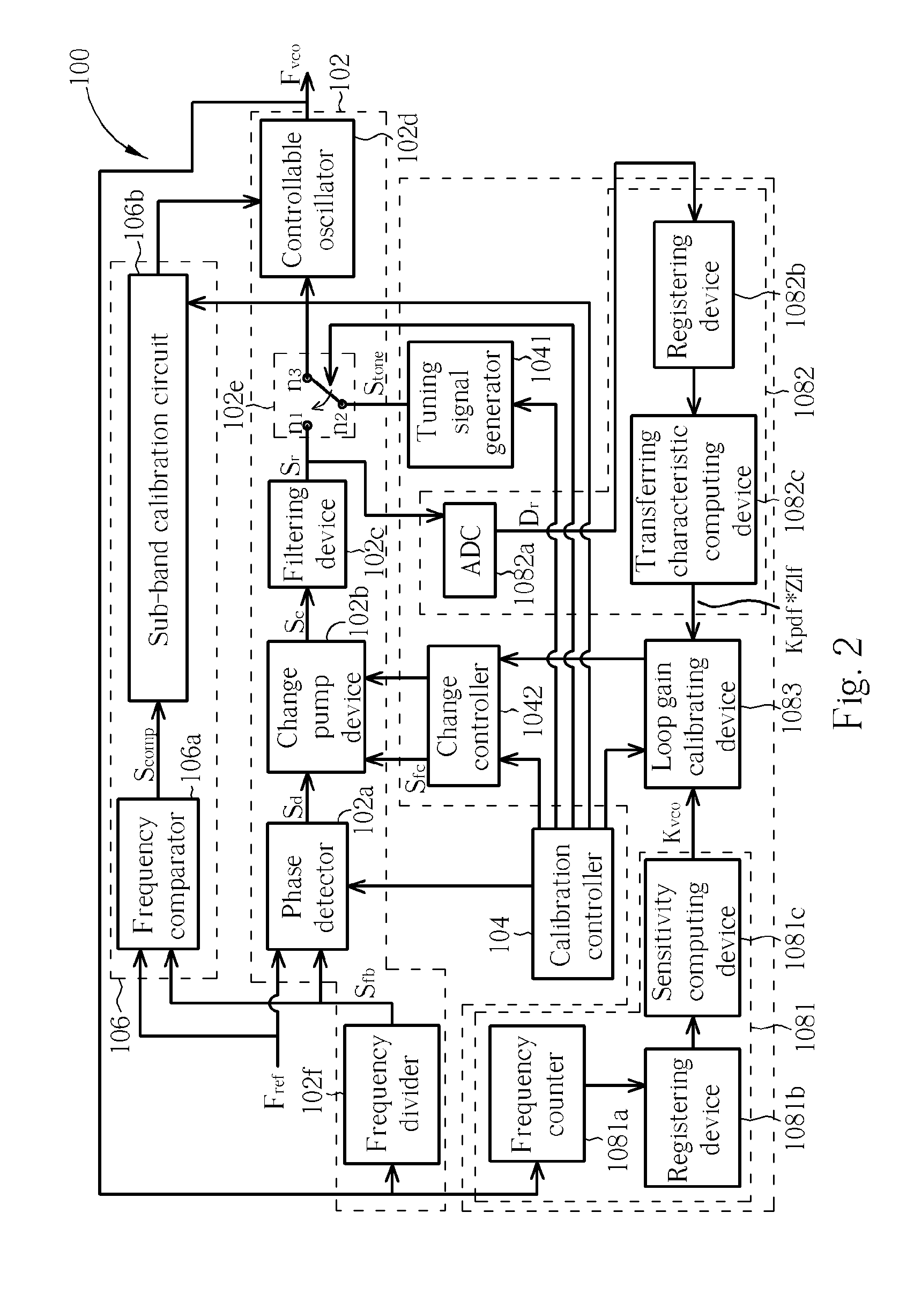
[0018]Please refer to FIG. 2. FIG. 2 is a diagram illustrating a signal generating apparatus 100 according to an embodiment of the present invention. The signal genera...


PUM


Abstract

A signal generating apparatus is disclosed. The signal generating apparatus includes a phase-locked loop device for generating a synthesized signal, wherein the phase-locked loop device includes a phase detector, a charge pump device, a filtering device, a controllable oscillator, and a switch device coupled to the controllable oscillator for selectively coupling the controllable oscillator to the filtering device or a tuning reference signal; a calibration controller generates a tuning reference signal and controls the switch device; and a first calibrator tunes the controllable oscillator into a predetermined sub-band according to a reference oscillating signal and a synthesized signal when the switch device couples the controllable oscillator to the tuning reference signal of the calibration controller.

Description

BACKGROUND[0001]The present invention relates to a signal generating apparatus, and more particularly to a phase-locked loop synthesizer with sub-band and loop gain calibration devices, and a method thereof.[0002]An electronic system or circuit always utilizes a frequency synthesizer to synchronize a system, where the frequency synthesizer always includes a frequency locking circuit, such as a phase-locked loop (PLL) circuit, to lock a specific signal to a specific frequency. As the system speed rapidly increases, it is difficult to maintain the locking speed of the frequency locking circuit. In fact, the locking speed of the frequency locking circuit is generally limited by the frequency of a reference clock signal. Therefore, it is problematic to apply a traditional frequency locking circuit to a high speed hopping system with high reference clock signal frequency.[0003]Furthermore, the loop bandwidth BW of the PLL circuit is maintained as stably as possible within a predetermined...

Claims


Application Information

Patent Timeline
IPC IPC(8): H03L7/087H03L7/08H03L7/085
CPCH03L7/087H03L7/18H03L7/113H03L7/0898
Inventor KE, LING-WEIYU, TAI-YUANCHEN, HSIN-HUNGLIN, TSER-YU
Owner MEDIATEK INC
Why Eureka
Eureka Blog
Learn More