Tiled passive matrix electro-luminescent display

a passive matrix and electroluminescent display technology, applied in the field of passive matrix electroluminescent display, can solve the problems of reducing the quality of the display, affecting the display, and consuming a lot of power, and achieve the effect of less power and higher resolution

Active Publication Date: 2009-03-19
GLOBAL OLED TECH
View PDF10 Cites 23 Cited by
  • Summary
  • Abstract
  • Description
  • Claims
  • Application Information

AI Technical Summary

Benefits of technology

[0013]While attempting to utilize a combination of tiling and multiline drive methods for passive matrix EL displays, it has been discovered that the existing multiline drive methods produce visible luminance artifacts at the boundary between adjacent tiles. The present invention allows one to utilize methods for driving multiple lines of a passive matrix EL display together with the methods for tiling EL displays to gain the combined advantages of each of these methods without introducing these visible artifacts. As the use of both tiling and multilin

Problems solved by technology

However, these displays tend to be relatively expensive due to the complexity of forming an active circuit at each light-emitting element and the thin film transistors that are often used within these active drive circuits are prone to defects, leading to lack of uniformity or threshold shifts over time, which degrade the quality of the display.
Unfortunately, these displays typically allow only one line of the display to be driven simultaneously, typically using pulse width modulation.
Further, it is typically necessary in these devices to discharge and charge the capacitance of each light-emitting element before each lighting cycle.
For these reasons, passive matrix, thin-film, coated electro-luminescent displays typically draw excessive amounts of power and often require drive voltages that are larger than can be provided by row and column drivers that are manufactured using low-cost si

Method used


Image

  • Tiled passive matrix electro-luminescent display
  • Tiled passive matrix electro-luminescent display
  • Tiled passive matrix electro-luminescent display

Examples


example 1

Comparative

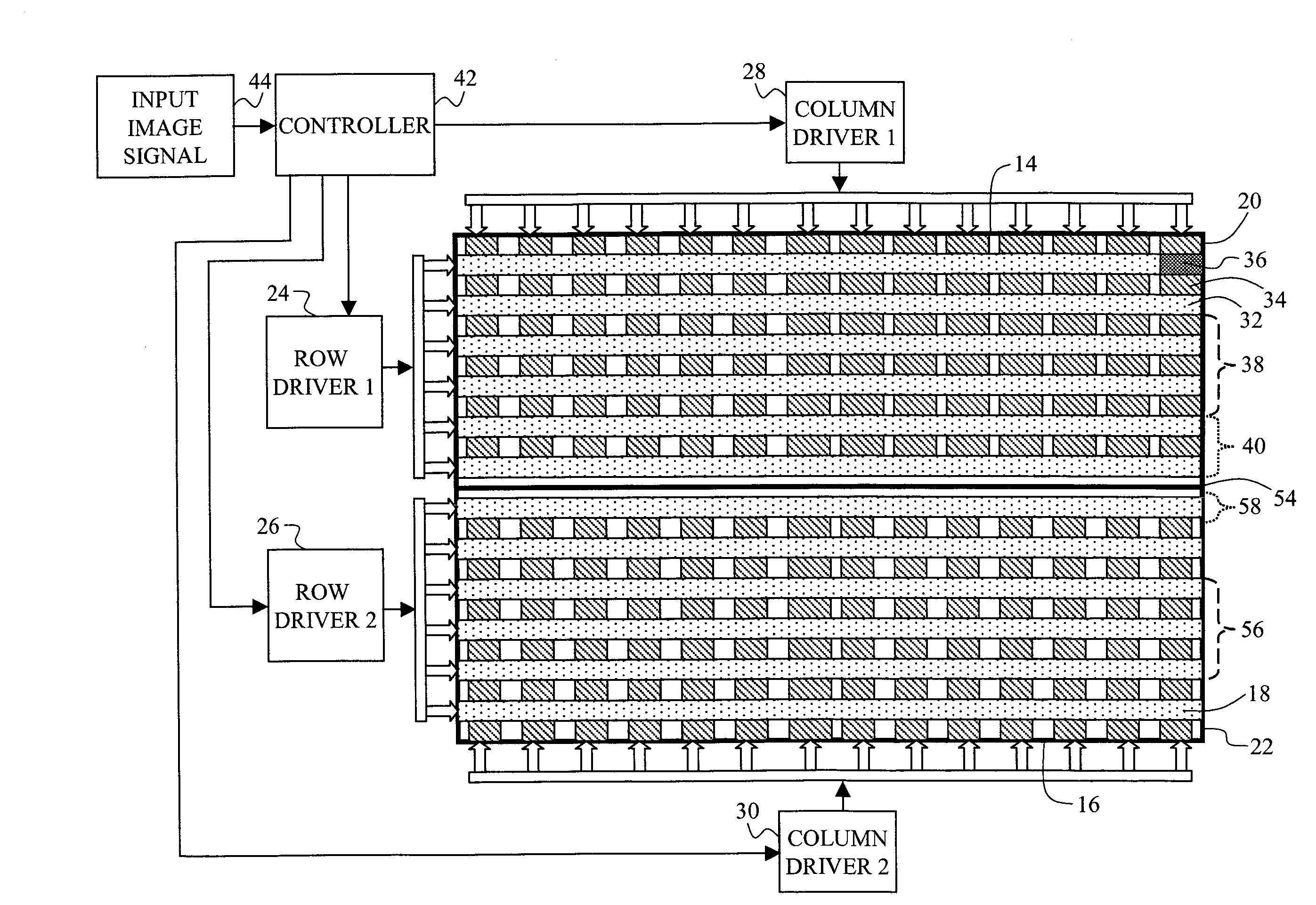
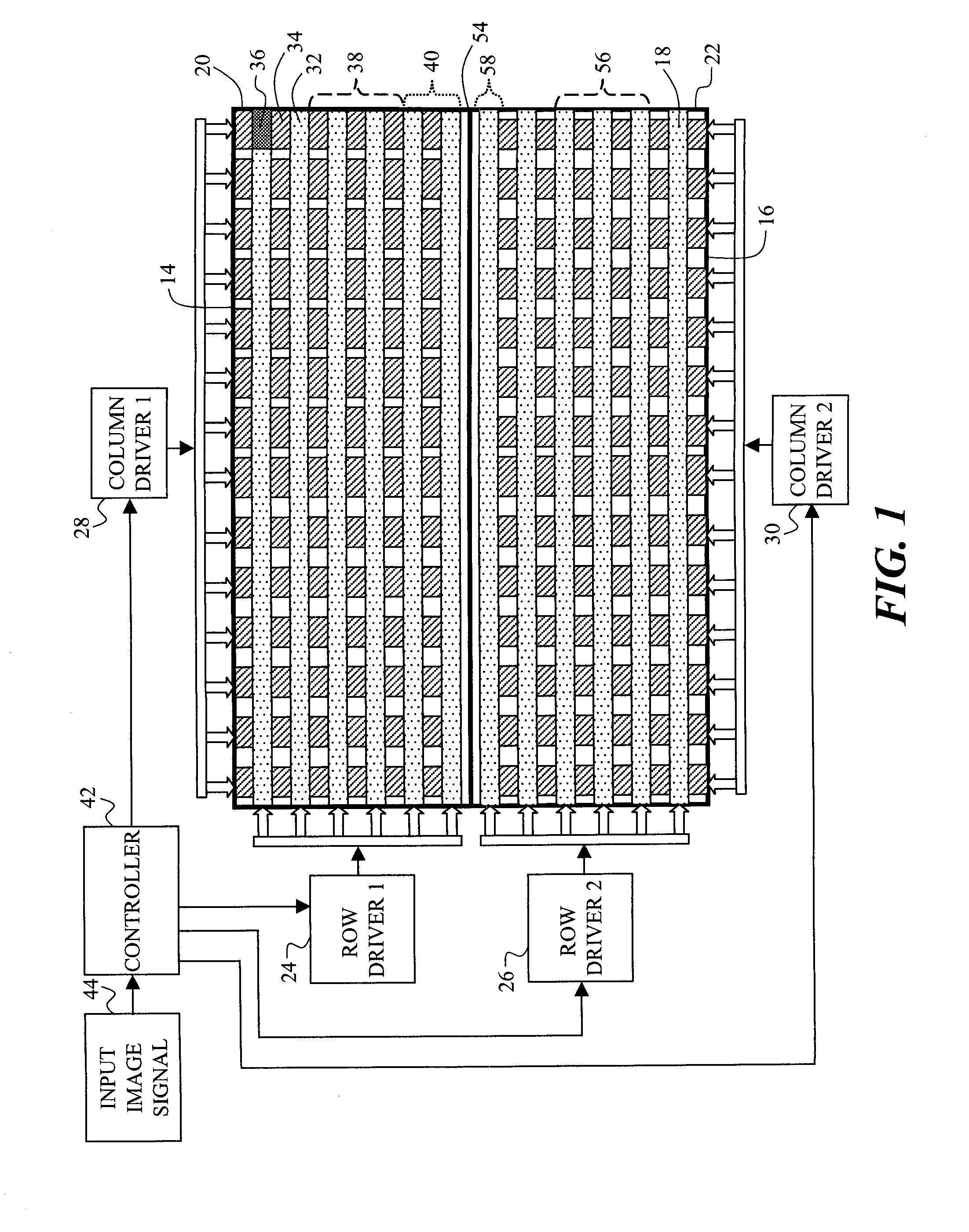
[0050]In this example, a display having two tiles 20, 22, each tile having 120 row electrodes 32 and 240 column electrodes 34 will be assumed. Further, it will be assumed that each tile has its own row driver and column driver. Further, each tile will have its own controller 42 and each controller will receive only the portion of the input image signal 44 that corresponds to the spatial locations of the light-emitting elements 36 within the tile 20, 22 that it controls. Therefore, the two controllers will not be able to respond to changes in luminance within the input image signal that occur in the input image signal that correspond to the spatial location of light-emitting elements in the adjacent tile. This design is consistent with prior art embodiments, in which the input image signal is parsed and delivered to each tile for rendering.

[0051]The input image signal 44 will include information for rendering two dark gray bars on a white background. The dark gray bars wil...

example 2

Inventive

[0053]In this example, a tiled, passive-matrix, EL display is created according to an embodiment of the present invention. It includes two EL tiles, each EL tile including an array of 120 rows and 240 columns of light-emitting elements, each light-emitting element being formed from a light-emitting layer that is sandwiched between an orthogonal array of row and column electrodes. The tiled, passive-matrix, EL display includes at least one row and column driver for controlling the flow of electrons between the row and column electrodes within each tile to control the emission of light from each of the light-emitting elements within each tile. The tiled, passive-matrix, EL display further is assumed to include one controller coupled to the row and column drivers for receiving an input image signal and for simultaneously providing a predetermined number of row drive signals to two or more row drivers within the two or more EL tiles, with a first exception that when the boundar...


PUM


Abstract

A tiled, passive-matrix, EL display, including two or more EL tiles, each EL tile including an array of rows and columns of light-emitting elements, each light-emitting element being formed from a light-emitting layer that is sandwiched between an orthogonal array of row and column electrodes wherein each of the two or more EL tiles further include at least one row driver; at least one column driver for operating in conjunction with each of the at least one row drivers to control the flow of electrons between the row and column electrodes to control the emission of light from each of the light-emitting elements, with a first exception that when the boundary between the two tiles is to be illuminated, then the number of rows of simultaneously illuminated rows of light-emitting elements within one tile is less than the predetermined number.

Description

CROSS REFERENCE TO RELATED APPLICATIONS[0001]Reference is made to commonly assigned U.S. patent application Ser. No. 11 / 737,736, filed Apr. 20, 2007, by Michael Eugene Miller et al., entitled “Passive Matrix Electro-Luminescent Display System”, the disclosure of which is incorporated herein.FIELD OF THE INVENTION[0002]The present invention relates to passive matrix electro-luminescent displays. Particularly, the present invention relates to a tiled passive matrix display that is driven without visible boundaries between adjacent tiles.BACKGROUND OF THE INVENTION[0003]Many display devices exist within the market today. Among the displays that are available are thin-film, coated, Electro-Luminescent (EL) displays, such as OLED displays. These displays can be driven using active matrix backplanes, which employ an array of active circuits. These active circuits control the flow of current to each light-emitting element in the display. However, these displays tend to be relatively expens...

Claims


Application Information

Patent Timeline
IPC IPC(8): G09G5/00G09G3/30
CPCG09G3/3216G09G2300/026G09G2300/06G09G2310/0205H01L27/3293G09G2310/0221G09G2320/0233G09G2330/021H01L27/3281G09G2310/021H10K59/17H10K59/18
Inventor MILLER, MICHAEL E.ARNOLD, ANDREW D.HAMILTON, JR., JOHN F.
Owner GLOBAL OLED TECH
Why Eureka
Try Eureka