
Programmable LED driver

a programmable led and driver technology, applied in the direction of instruments, static indicating devices, electroluminescent light sources, etc., can solve the problems of increased bill-of-materials (bom) cost of the overall led driver circuitry, board space waste, cost,

Active Publication Date: 2009-03-19
IXYS CH
View PDF9 Cites 15 Cited by
  • Summary
  • Abstract
  • Description
  • Claims
  • Application Information

AI Technical Summary

Benefits of technology

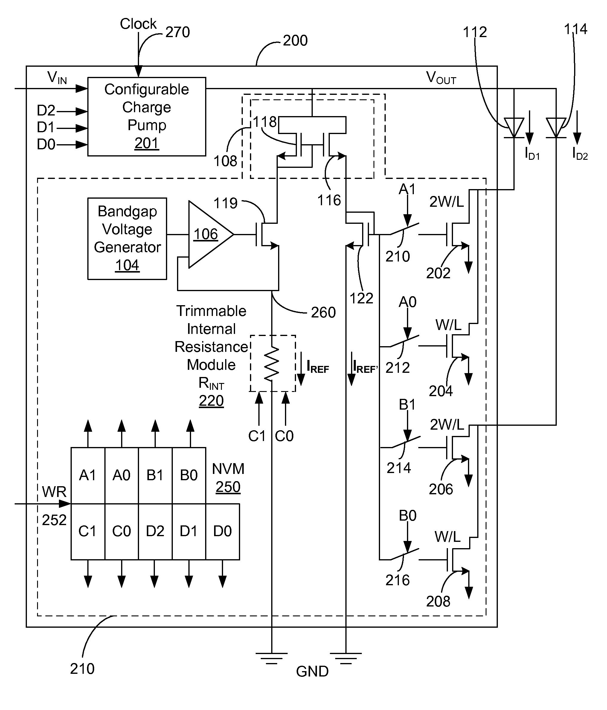
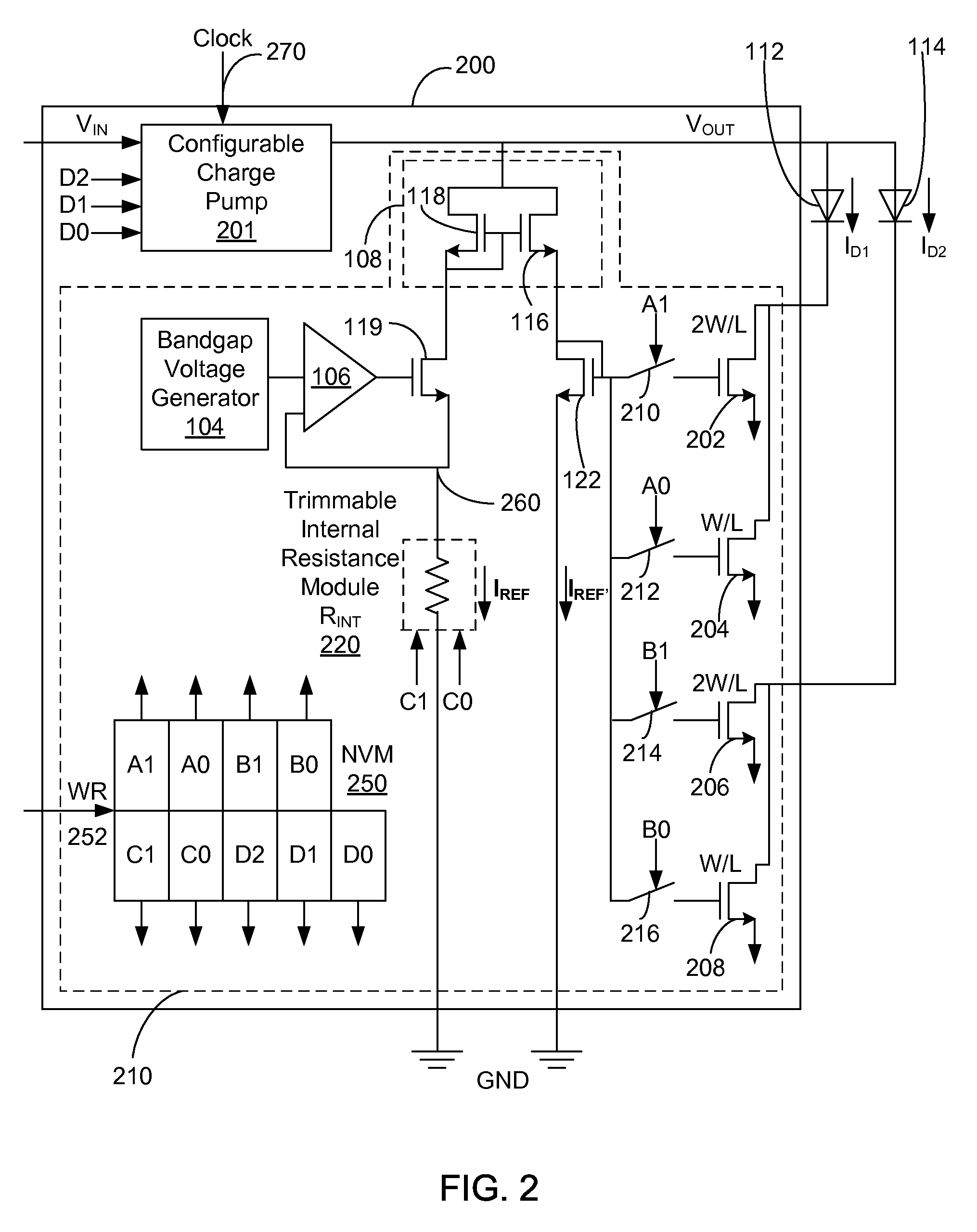
[0013]Embodiments of the present invention include an LED driver with an embedded non-volatile memory (NVM) capable of being programmed and storing control data for setting a variety of features of the LED driver, such as but not limited to the maximum current for driving the LEDs, analog parameters such as the resistance of the internal resistor for setting the reference current for the LEDs, and operation modes of the charge pump of the LED driver. This enables the implementation of multiple LED driver product options without the need for different metallization steps during the fabrication process for the LED driver.
[0017]The present invention has the advantage that a variety of features of the LED driver, such as the LED current, internal resistance for setting the reference current for the LEDs, and the operation modes of the charge pump, and potentially a variety of other analog parameters of the LED driver may be conveniently set simply by programming the LED driver with the appropriate control data value in the non-volatile memory. Thus, an LED driver with different functionalities and features can be implemented as a single IC from the same die in the semiconductor fabrication process without having to go through different metallization processes for the different functionalities during the fabrication of the IC for the LED driver.

Problems solved by technology

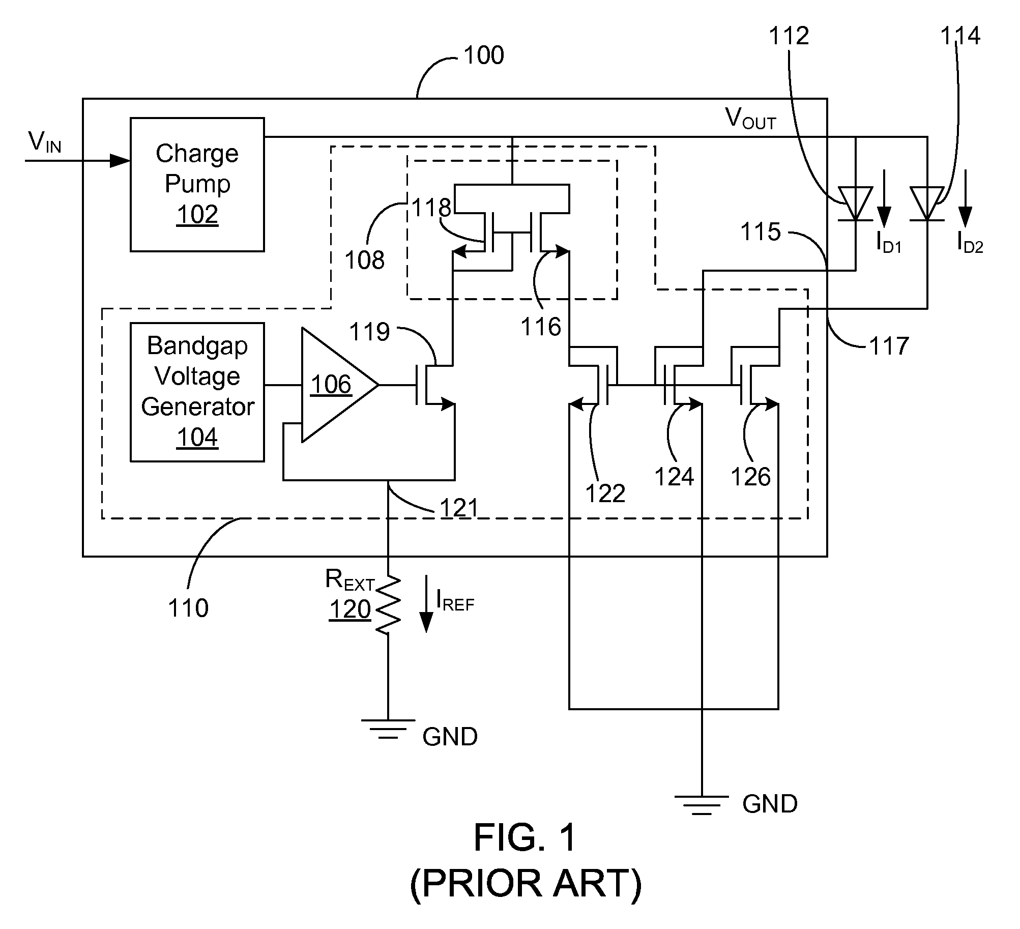
Such external resistor 120 adds a pin to the LED driver IC (integrated circuit), extra board space for the overall LED driver circuitry, and results in an increase in the Bill-of-Materials (BOM) cost for the overall LED driver circuitry.
The resistor 120 is typically external to the LED driver 100 in order to have its resistance value changed, which results in waste of a pin, board space, and cost, as explained above.

Method used


Image

  • Programmable LED driver
  • Programmable LED driver
  • Programmable LED driver

Examples


Embodiment Construction

[0024]The Figures (FIG.) and the following description relate to preferred embodiments of the present invention by way of illustration only. It should be noted that from the following discussion, alternative embodiments of the structures and methods disclosed herein will be readily recognized as viable alternatives that may be employed without departing from the principles of the claimed invention.

[0025]Reference will now be made in detail to several embodiments of the present invention(s), examples of which are illustrated in the accompanying figures. It is noted that wherever practicable similar or like reference numbers may be used in the figures and may indicate similar or like functionality. The figures depict embodiments of the present invention for purposes of illustration only. One skilled in the art will readily recognize from the following description that alternative embodiments of the structures and methods illustrated herein may be employed without departing from the pr...


PUM


Abstract

An LED driver includes an embedded non-volatile memory (NVM) capable of being programmed and storing control data for setting a variety of features of the LED driver, such as the maximum current for driving the LEDs, analog parameters such as the resistance of the internal resistor for setting the reference current for the LEDs, and the operation modes of the charge pump of the LED driver. This enables implementation of multiple LED driver product options without the need for different metallization steps during the fabrication process for the LED driver.

Description

BACKGROUND OF THE INVENTION[0001]1. Field of the Invention[0002]The present invention relates to an LED (Light-Emitting Diode) driver, and more specifically to a programmable LED driver with an embedded non-volatile memory storing control data for custom programming of a variety of features of the LED driver.[0003]2. Description of the Related Arts[0004]White LEDs are being used increasingly in display devices. For example, some modern liquid crystal display (LCD) devices use white LEDs as the backlight for the LCD display. These LEDs are typically driven by an LED driver. White LED drivers are typically constant current devices where a constant sink current is fed through the white LEDs to provide a constant luminescence. The anode of the white LEDs is driven by a charge pump circuit.[0005]FIG. 1 illustrates a conventional LED driver 100 driving LEDs 112, 114. For example, the LEDs 112, 114 can be white LEDs. The LED driver 100 includes 2 main circuit blocks, a charge pump 102 and ...

Claims


Application Information

Patent Timeline
Patent Type & Authority Applications(United States)
IPC IPC(8): G09G3/32G09G5/00H05B44/00
CPCH05B33/0827H05B33/0818H05B45/46H05B45/20H05B45/37
Inventor MITTAL, ROHITMONTANARI, DONATO
Owner IXYS CH
Learn More