Optical transmitter and control method thereof

a technology of optical transmitter and control method, applied in the field of optical communication system, can solve the problems of inability to perfectly return the quantum state of the once-observed photon to the state before observation, and the cipher according to these methods is in constant danger of being broken,

Active Publication Date: 2009-03-19
NEC CORP
View PDF10 Cites 32 Cited by
  • Summary
  • Abstract
  • Description
  • Claims
  • Application Information

AI Technical Summary

Benefits of technology

[0029]An object of the present invention is to provide an optical transmitter with a new configuration that can accomplish modulation with three values in inten

Problems solved by technology

The Internet, which is growing rapidly, is convenient, but, in actual fact, there is great apprehension about its security.
However, these are cryptographic communication methods that guarantee the security of communication based on computational complexity.
Ciphers according to these methods are in constant jeopardy of being broken with the advent of vast computing power or a cryptanalysis algorithm.
If an eavesdropper existing on a transmission path eavesdrops on the information by, for example, tapping a photon being transmitted, it is impossible to perfectly return the quantum state of the once-observed photon to the state before observation, according to Heisenberg's uncertainty principle.
However, QKD methods of such a round-trip type are unsuitable to increase the key sharing rate because phase modulators for modulating the phase of a photon pulse need to be used in two ways.
In addition, there is also a demerit that the signal-to-noise ratio of a photon signal is degraded because the occurrence of backscattering light in a transmission path is inevita

Method used


Image

  • Optical transmitter and control method thereof
  • Optical transmitter and control method thereof
  • Optical transmitter and control method thereof

Examples


first exemplary embodiment

1. FIRST EXEMPLARY EMBODIMENT

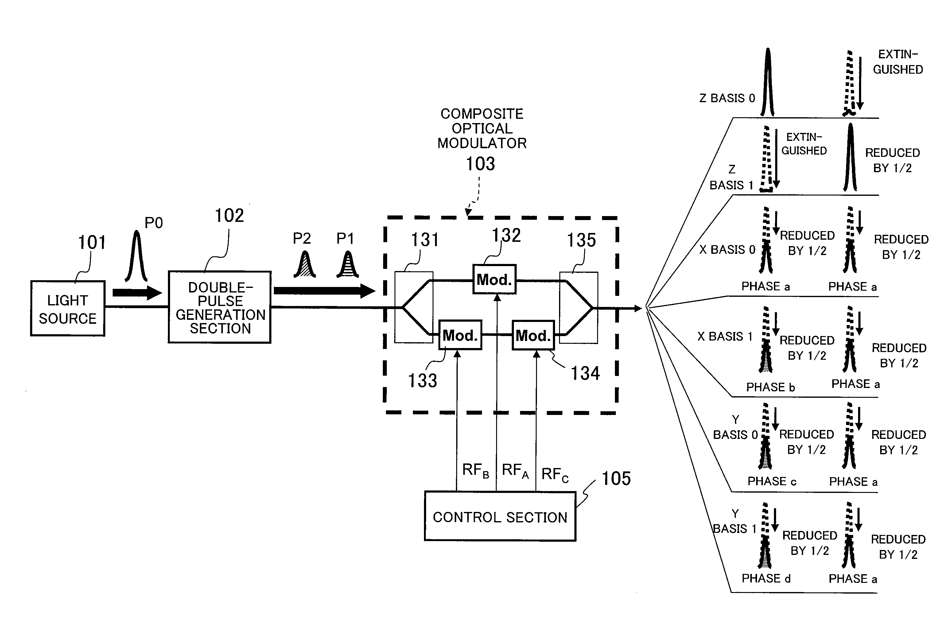
[0059]According to a first exemplary embodiment of the present invention, a composite modulator includes a Mach-Zehnder intensity modulator placed in one of the paths (arms) of a Mach-Zehnder interferometer, and a Mach-Zehnder intensity modulator and phase modulator placed in the other path (the other arm). That is, in FIG. 4, the first optical modulator 132 and second optical modulator 133 are Mach-Zehnder intensity modulators, and the third optical modulator 134 is a phase modulator.

1.1) Configuration

[0060]FIG. 5A is a block diagram showing the schematic configuration of an optical transmitter according to the first exemplary embodiment of the present invention, and FIG. 5B is a signal constellation diagram representing the signals according to this transmitter. An optical pulse P0 generated by a light source 101 is split into double pulses P1 and P2 by a double-pulse generation section (here, a PLC AMZ interferometer) 102. After the double pulses P1 a...

second exemplary embodiment

2. SECOND EXEMPLARY EMBODIMENT

[0083]A composite modulator according to a second exemplary embodiment of the present invention includes a Mach-Zehnder intensity modulator placed in one of the paths (arms) of a Mach-Zehnder interferometer, and two phase modulators placed in the other path (the other arm). That is, in FIG. 4, the first optical modulator 132 is a Mach-Zehnder intensity modulator, and the second optical modulator 133 and third optical modulator 134 are phase modulators.

2.1) Configuration

[0084]FIG. 9A is a block diagram showing the schematic configuration of an optical transmitter according to the second exemplary embodiment of the present invention, and FIG. 9B is a signal constellation diagram showing the signal points according to this transmitter. The second exemplary embodiment is different from the first exemplary embodiment shown in FIG. 5A only in the configuration of the composite modulator 301, and the other circuitry is the same. Accordingly, the same circuit e...

third exemplary embodiment

3. THIRD EXEMPLARY EMBODIMENT

[0107]A composite modulator according to a third exemplary embodiment of the present invention includes a phase modulator placed in one of the paths (arms) of a Mach-Zehnder interferometer, and two phase modulators placed in the other path (the other arm). That is, in FIG. 4, the first optical modulator 132, second optical modulator 133, and third optical modulator 134 are all phase modulators.

3.1) Configuration

[0108]FIG. 11A is a block diagram showing the schematic configuration of an optical transmitter according to the third exemplary embodiment of the present invention, and FIG. 11B is a signal constellation diagram showing the signal points according to this transmitter. The third exemplary embodiment is different from the first exemplary embodiment shown in FIG. 5A only in the configuration of a composite modulator 401, and the other circuitry is the same. Accordingly, the same circuit elements as in FIG. 5A are denoted by the same reference numera...


PUM


Abstract

An optical transmitter which modulates the phases and intensities of double pulses and then transmits them, includes a branching section which branches each of the input double pulses to first and second paths, a first optical modulator placed in the first path, second and third optical modulators placed in series in the second path, and a combining section which combines the double pulses having traveled through the first path with the double pulses having traveled through the second path to output double pulses. A control section controls such that each of the first and second optical modulators performs any one of relative intensity modulation and relative phase modulation on the double pulses passing through, and the third optical modulator performs relative phase modulation on the double pulses passing through.

Description

BACKGROUND OF THE INVENTION[0001]1. Field of the Invention[0002]This application is based upon and claims the benefit of priority from Japanese Patent Application No. 2007-228510, filed on Sep. 4, 2007, the disclosure of which is incorporated herein in its entirety by reference.[0003]The present invention relates to an optical communication system in which an optical pulse is phase- and intensity-modulated and then transmitted and, more particularly, to an optical transmitter and a method for controlling a composite modulator used in the optical transmitter.[0004]2. Description of the Related Art[0005]The Internet, which is growing rapidly, is convenient, but, in actual fact, there is great apprehension about its security. The necessity for high-degree cryptographic technologies is ever increasing to maintain secrecy in communication. The cryptographic methods that are currently used in general are broadly classified into secret key cryptography, such as Data Encryption Standard (DE...

Claims


Application Information

Patent Timeline
IPC IPC(8): H04B10/04H04B10/516H04B10/524H04B10/54H04B10/556H04B10/61H04B10/70
CPCH04B10/30H04B10/5051H04B10/548H04B10/541H04B10/5053
Inventor TANAKA, AKIHIROTAJIMA, AKIOTAKAHASHI, SEIGOMAEDA, WAKAKO
Owner NEC CORP
Why Eureka
Try Eureka