Lever lock type connector

a technology of lever lock and connector, which is applied in the direction of coupling device connection, coupling/disconnecting parts engagement/disengagement, electrical apparatus, etc., can solve the problems of oxidation, abraded plating, backlash due to vibration between the outer housing b, etc., and achieve the effect of preventing backlash and enhancing the vibration resistance of the connector

Inactive Publication Date: 2009-03-19
HITACHI CABLE
View PDF21 Cites 37 Cited by
  • Summary
  • Abstract
  • Description
  • Claims
  • Application Information

AI Technical Summary

Benefits of technology

[0028]In the embodiments of the invention, by turning only the rotating lever, locking force can be effected in a direction toward the outer housings from the lateral sides of the connector. Therefore, backlash can be effectively prevented in a direction orthogonal to the joining direction of the connector housings without increasing the number of steps for joining the connector housings together.
[0029]In other words, without increasing the contact force (or insertion force) between the male and female terminals inside the outer housings, abrasion between the male and female terminals due to vibration can be prevented. Thus, the joining operation can be easy conducted without increasing the size of the rotating lever as a toggle mechanism.
[0030]The locking member may be provided with an elastic member at a part for contacting the lateral side of the other outer housing. Thereby, the vibration resistance of the connector can be further enhanced.

Problems solved by technology

However, when this connector is used in an engine room of a vehicle which is subjected to vibration, backlash occurs due to the vibration between the outer housings 1 and 2.
Thus, a problem arises that tin or silver plating is abraded at the contact portion, a copper base is thereby exposed and oxidized, and the contact portion of the male terminal 4 and the female terminal increases in resistance.
However, in the connector as described in JP-A-2006-331996, since elastic force by the coil spring acts in a direction for separating the connectors, a problem arises that operability for joining the connector housings together lowers.
In addition, although the backlash can be reduced in the joining direction of the connector housings, other backlash cannot be sufficiently reduced in a direction orthogonal to the joining direction of the connector housings.
Thus, backlash between the male and female terminals can occur in the direction orthogonal to the joining direction, so that abrasion between the terminals cannot be eliminated completely.

Method used


Image

  • Lever lock type connector
  • Lever lock type connector
  • Lever lock type connector

Examples


first embodiment

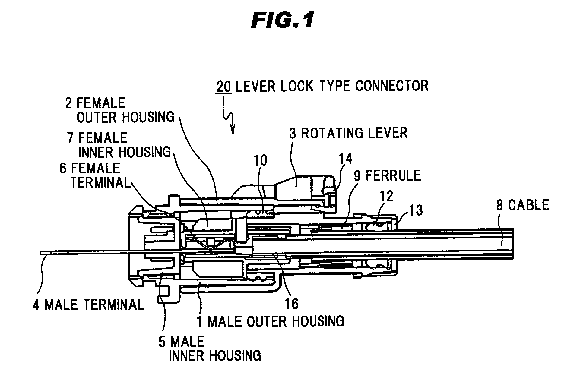
[0045]The first preferred embodiment according to the present invention will be explained in detail referring to FIG. 1 to FIG. 5.

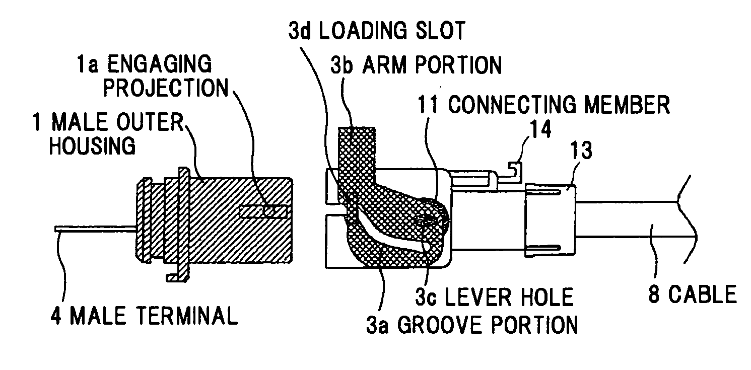
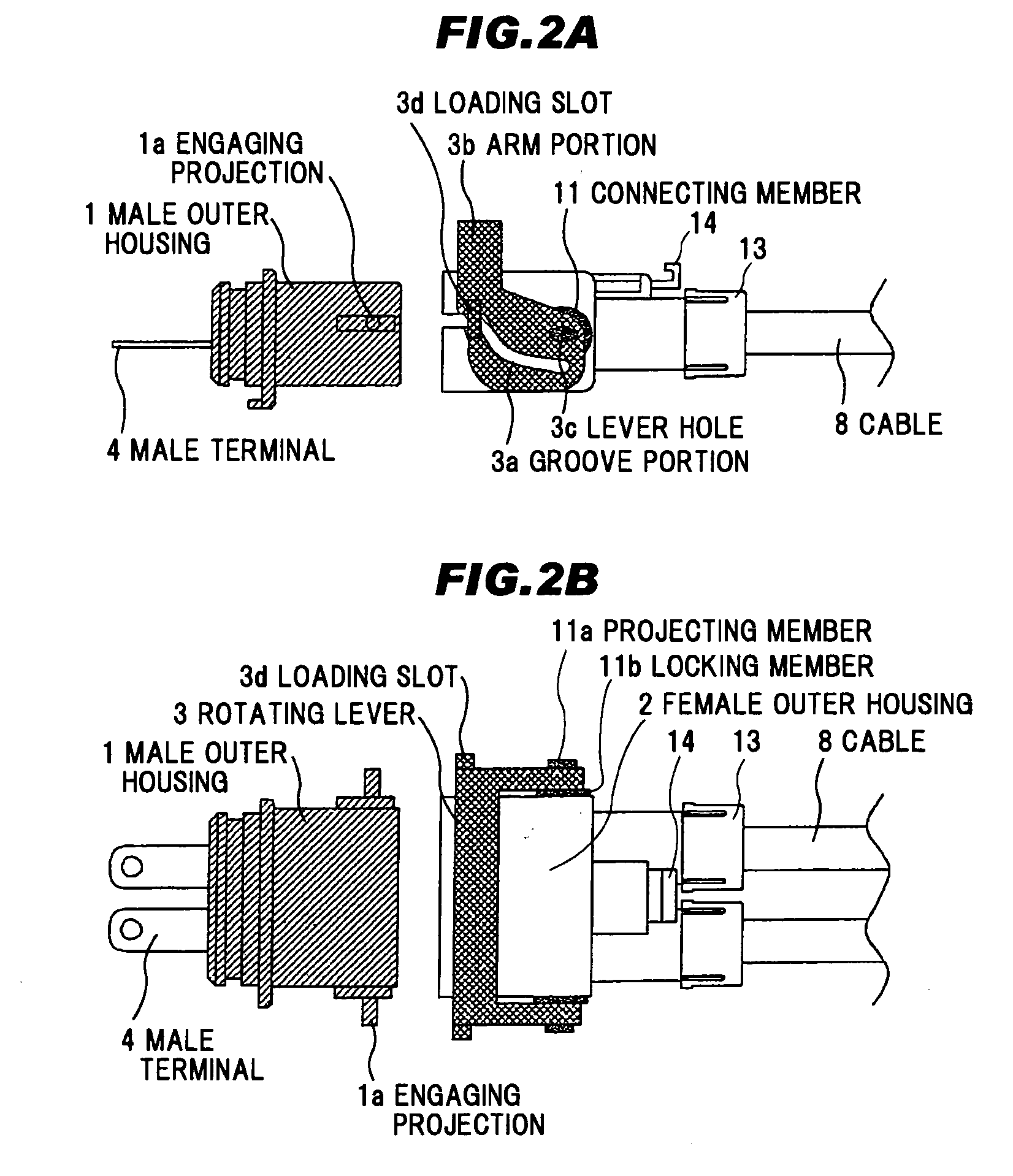
[0046]FIG. 1 shows the cross sectional structure of a lever lock type connector 20 in the first embodiment when being joined. The lever lock type connector 20 is composed of a male outer housing 1, and a female outer housing 2 engageable with the male outer housing 1. A device-side connector having the male outer housing 1 is attached to a device (not shown), and a cable-side connector having the female outer housing 2 is attached to a cable 8.

[0047]The device-side connector has a structure that a male inner housing 5 of an insulating resin is fixed to the outer periphery of a male terminal 4 having a tab terminal structure, and the male inner housing 5 is fixed to the male outer housing 1 of aluminum.

[0048]The cable-side connector has a structure that a female inner housing 7 of an insulating resin is fixed to the outer periphery of a female terminal 6 h...

second embodiment

[0066]The second preferred embodiment according to the present invention will be explained in detail referring to FIG. 6A to FIG. 7B.

[0067]FIG. 6A shows a side view of the lever lock type connector of the second embodiment before the connector joining. In the first embodiment, the connecting member 11 for ratably connecting the rotating lever 3 to the female outer housing 2 is integrated with the locking member 11b for locking the outer housings 1 and 2. In the second embodiment, a connecting member 17 for rotatably connecting the rotating lever 3 to the female outer housing 2 is separated from a locking member 18 for locking the outer housings 1 and 2. The other components are the same as the first embodiment.

[0068]Following is a detailed explanation for the connecting member 17 and the locking member 18 which are distinctive in the second embodiment. FIG. 6B shows an enlarged top view of a periphery of the locking member 18 before joining the connector.

[0069]A projecting member 17...


PUM


Abstract

A lever lock type connector includes a pair of outer housings including connecting terminals for an electrical connection, the pair of outer housings being joined each other by a rotating operation of a rotating lever in a state that the rotating lever rotatably supported by one of the pair of outer housings is engaged with an engaging portion of an other of the pair of outer housings, and a locking member that is provided on the one of the pair of outer housings and movable towards a sidewall of the other of the pair of outer housings. The locking member is adapted to move towards the sidewall of the other of the pair of outer housings in conjunction with the rotating operation of the rotating lever so as to contact the sidewall of the other of the pair of outer housings.

Description

[0001]The present application is based on Japanese Patent Application No. 2007-240376 filed on Sep. 18, 2007, the entire contents of which are incorporated herein by reference.BACKGROUND OF THE INVENTION[0002]1. Field of the Invention[0003]The present invention relates to a connector with a vibration-proofing structure and, in particular, to a lever lock type connector that a pair of connector housings can be joined by turning a lever.[0004]2. Related Art[0005]FIG. 8 shows a structure of a conventional connector used for electrical connection among a battery, an inverter and a motor, which is a hybrid system for a hybrid car. A male outer housing 1 surrounds a male inner housing 5, furthermore, the male inner housing 5 surrounds a male terminal 4. Furthermore, an engaging projection 1a is provided on both sidewalls of the male outer housing 1.[0006]In the same way, a female outer housing 2 surrounds a female inner housing (not shown), furthermore, the female inner housing (not shown...

Claims


Application Information

Patent Timeline
Patent Type & Authority Applications(United States)
IPC IPC(8): H01R13/62
CPCH01R13/62955H01R13/62938
Inventor SUZUKI, SACHIO
Owner HITACHI CABLE
Why Eureka
Try Eureka