
Chemically-Assisted Alignment of Nanotubes Within Extensible Structures

a nanotube and extensible technology, applied in the field of nanotube substantially aligning, can solve the problems of cumbersome nanotube alignment issues prior to the formation of extensible structures, inconvenient fabrication process, and inability to align nanotubes well, etc., to achieve the effect of increasing electrical and thermal conductivity and enhancing conta

Active Publication Date: 2009-03-19
NANCOMP TECHNOLOGIES INC
View PDF99 Cites 53 Cited by
  • Summary
  • Abstract
  • Description
  • Claims
  • Application Information

AI Technical Summary

Benefits of technology

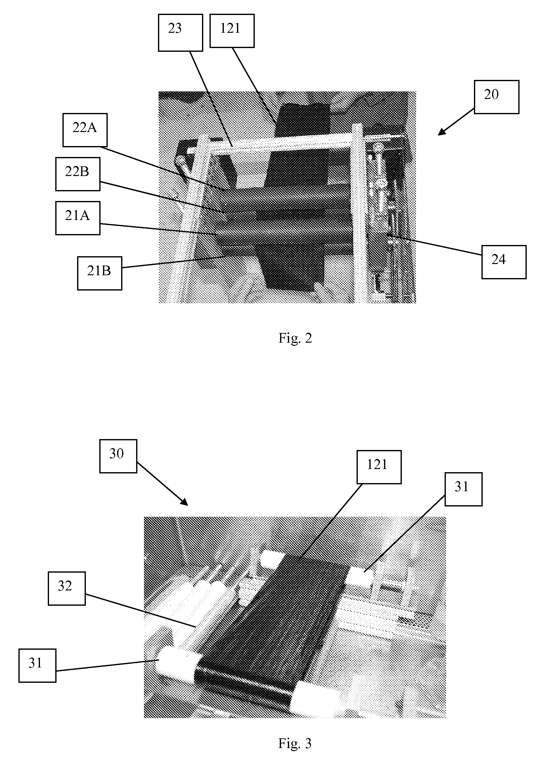
The present invention provides a method for aligning nanotubes within an extensible structure, such as a non-woven sheet, by adding a chemical to the structure and stretching it. The stretched structure exhibits enhanced contacts between adjacent nanotubes, resulting in increased electrical and thermal conductivity, as well as tensile strength. The amount of stretch can be from about 5 percent to several times the original length of the structure. The invention also provides a system for aligning nanotubes within an extensible structure using a pinch roller stretching apparatus with gears or stepper motors to create a difference in roller velocities. The system may also include a mechanism for wetting the structure to help in the stretching process.

Problems solved by technology

In other words, the nanotubes within these extensible structures may not be well aligned, particularly for the non-woven sheets.
To address the nanotube alignment issue prior to the formation of the extensible structure can be cumbersome, expensive, and cost prohibitive in connection with the fabrication process.

Method used


Image

  • Chemically-Assisted Alignment of Nanotubes Within Extensible Structures
  • Chemically-Assisted Alignment of Nanotubes Within Extensible Structures
  • Chemically-Assisted Alignment of Nanotubes Within Extensible Structures

Examples


example i

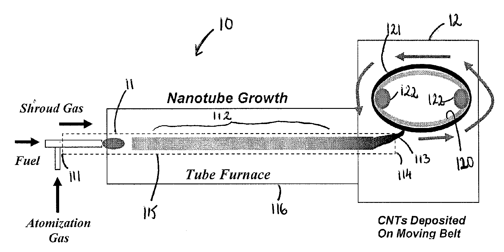
[0051]A single wall carbon nanotube non-woven sheet was produced by CVD deposition on a moving belt. This non-woven sheet (i.e., extensible structure) had dimensions of about 8 inches by about 36 inches, with an area density of about 1 mg / cm2. The approximate volumetric density of this non-woven sheet was about 0.2 g / cm3. This non-woven sheet was mounted in system 30 of FIG. 3, and sprayed with a solution of DMF and ZetaSperse. The solution of DMF and ZetaSperse was allowed to soak in for a period of about 10 minutes. The non-woven sheet was then stretched on system 30 at an elongation rate of about 1 inch / hr at a rotation rate of approximately 7 rpm.

[0052]Following the stretching, the non-woven sheet was soaked in acetone, allowed to air dry, and then baked in air at a temperature of 350° C. for about 3 hours.

[0053]Samples of this stretched non-woven sheet were taken from which property measurements were made. The results of the measurements are provided in Table 3.

TABLE 3PropertyB...

example ii

[0054]A partially spun yarn made of single wall carbon nanotubes was produced by a CVD process, similar to that described in U.S. patent application Ser. No. 11 / 488,387, incorporated herein by reference.

[0055]With reference now to FIG. 5, under steady-state production using a CVD process of the present invention, nanotubes 51 may be collected from within a synthesis chamber 52 and a yarn 53 may thereafter be formed. Specifically, as the nanotubes 51 emerge from the synthesis chamber 52, they may be collected into a bundle 54, fed into intake end 55 of a spindle 56, and subsequently spun or twisted into yarn 53 therewithin. It should be noted that a continual twist to the yarn 53 can build up sufficient angular stress to cause rotation near a point where new nanotubes 51 arrive at the spindle 56 to further the yarn formation process. Moreover, a continual tension may be applied to the yarn 53 or its advancement into collection chamber 58 may be permitted at a controlled rate, so as t...


PUM

PropertyMeasurementUnit
temperatureaaaaaaaaaa

Abstract

A method and system for aligning nanotubes within an extensible structure such as a yarn or non-woven sheet. The method includes providing an extensible structure having non-aligned nanotubes, adding a chemical mixture to the extensible structure so as to wet the extensible structure, and stretching the extensible structure so as to substantially align the nanotubes within the extensible structure. The system can include opposing rollers around which an extensible structure may be wrapped, mechanisms to rotate the rollers independently or away from one another as they rotate to stretch the extensible structure, and a reservoir from which a chemical mixture may be dispensed to wet the extensible structure to help in the stretching process.

Description

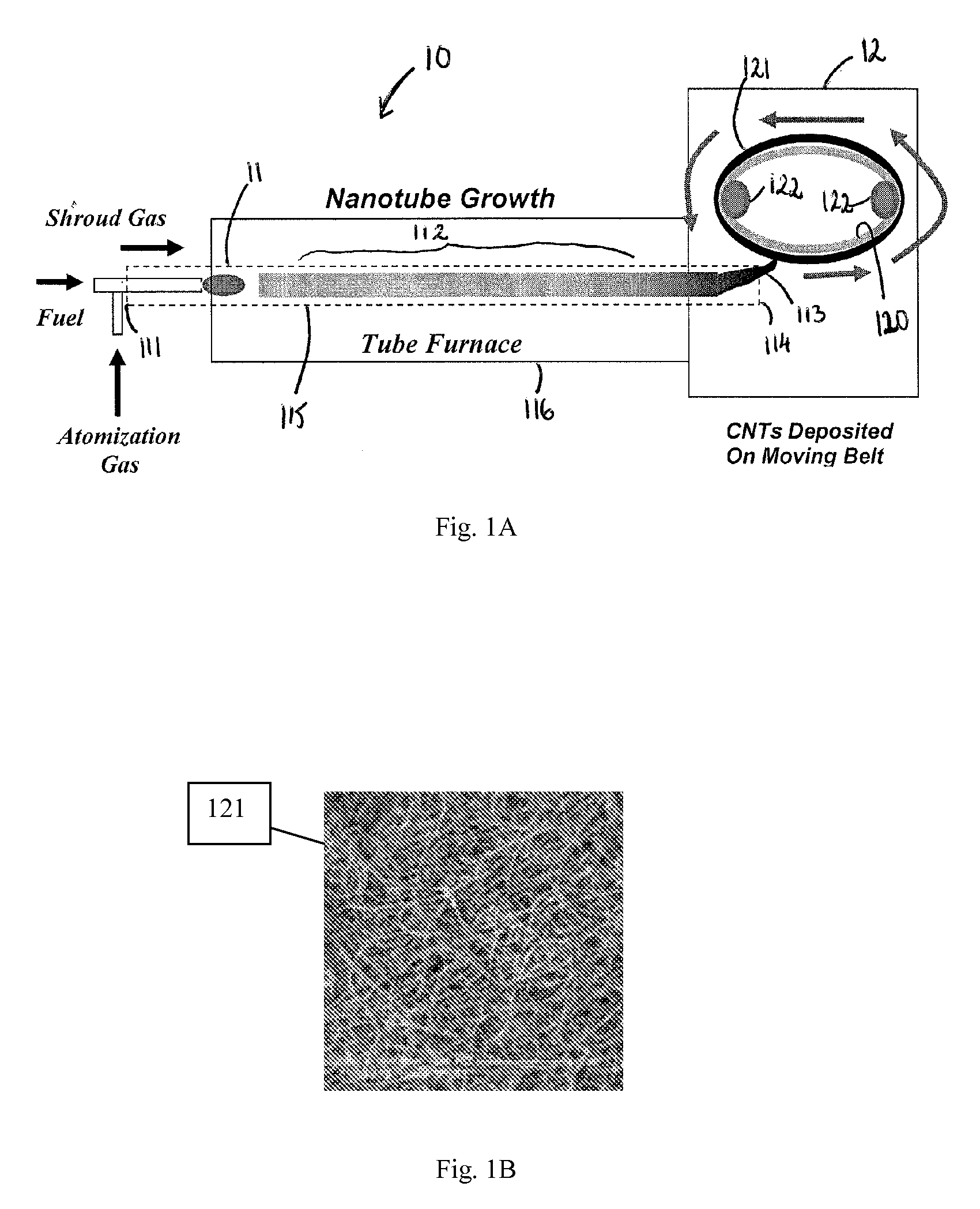
RELATED U.S. APPLICATION(S)[0001]The present invention claims priority to U.S. Provisional Application Ser. No. 60 / 958,758, filed Jul. 9, 2007, which application is hereby incorporated herein by reference.TECHNICAL FIELD[0002]The present invention relates to methods for alignment of nanotubes, and more particularly, to methods of substantially aligning nanotubes within extensible structures, such as yarns or non-woven sheets made from nanotubes.BACKGROUND ART[0003]Nanotubes may be fabricated using a variety of approaches. For example, nanotubes can be produced by conducting chemical vapor deposition (CVD) in such a manner that the nanotubes can be caused to deposit either on a moving belt or cylinder, where the nanotubes consolidate so as to form a non-woven sheet. Alternatively, the nanotubes can be taken up by a spinning device and spun into a yarn. Nanotubes collected as yarns, non-woven sheets, or similar extensible structures can also be fabricated by other means. For instance,...

Claims


Application Information

Patent Timeline
Patent Type & Authority Applications(United States)
IPC IPC(8): D04H13/00B29C55/22B29C49/00D04H3/04
CPCB29C49/02B29C51/004B29C51/02B29C55/00Y10T428/2913B29C2791/007B29K2105/162D04H1/42D04H1/4242B29C2791/006D04H1/4234Y10T428/249921Y10T442/696Y10T442/602D04H1/43838
Inventor LASHMORE, DAVID S.BRADEN, ROBERTHART, ANASTASIOS JOHNWELCH, JOHN
Owner NANCOMP TECHNOLOGIES INC
Learn More