Workflow-Enabled Provider

Active Publication Date: 2009-03-19
RICOH KK
View PDF24 Cites 69 Cited by
  • Summary
  • Abstract
  • Description
  • Claims
  • Application Information

AI Technical Summary

Benefits of technology

[0007]The present invention overcomes the deficiencies of the prior art with a distributed workflow-enabled system having a workflow-enabled provider. The workflow-enabled provider includes a service provider and a workflow manager interface unit. The service provider is any one of a conventional type such as a multifunction printer, a printer, a scanner or web service. The workflow manager interface unit couples the service provider to a workflow manager to provide the automatic discovering, distributed processing and dynamic user interface generating functionality of the present invention. The workflow manager interface unit includes a communication manager, a process control module and a user interface module. The communication manager has an advertisement monitor, a

Problems solved by technology

However, one problem with existing configurations of these devices is that in order to use each device on the network, the user must know about the device's existence, must load different software or other drivers to communicate with each device, and has no flexibility on how to interact with the devices.
Thus, users typically only interact with a small number of devices on the network and do not use many resources available on the network.
While many of these devices have an ability to communicate over a network whether it be wired or wireless, their ability to interface with peripheral devices is significantly limited because each peripheral device requires compliance with different data communication protocols, has its own application interface and data has to be in a format specific to that peripheral and often different from the format of other peripherals.
One particular problem with current environ

Method used


Image

  • Workflow-Enabled Provider
  • Workflow-Enabled Provider
  • Workflow-Enabled Provider

Examples


first embodiment

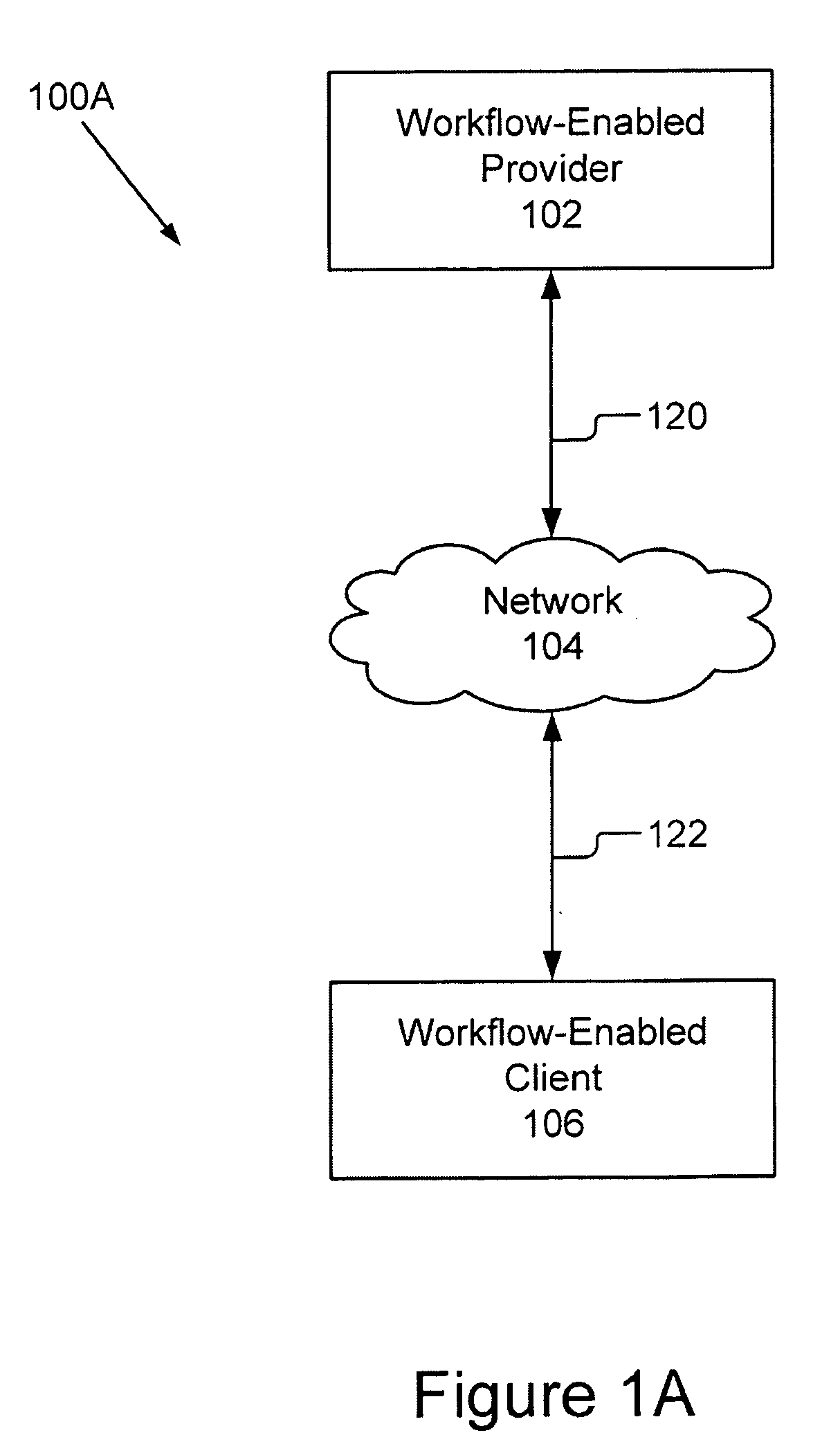
[0050]FIGS. 1A-1E show various embodiments of a distributed workflow-enabled system 100A-100E configured in accordance with the present invention. Referring now to FIG. 1A, the distributed workflow-enabled system 100A comprises: a workflow-enabled provider 102, a network 104 and a workflow-enabled client 106. FIG. 1A illustrates a minimal configuration for the distributed workflow-enabled system 100 of the present invention with one workflow-enabled provider 102 and one workflow-enabled client 106. The workflow-enabled provider 102 is coupled communicatively to the network 104 by signal line 120. The workflow-enabled client 106 communicatively is coupled by signal line 122 to the network 104. The workflow-enabled provider 102 can perform any variety of service operations depending on its hardware, software and connectivity. The service operations of the workflow-enabled provider 102 include but are not limited to scanning, print, photographing, copying, facsimile transmission, optic...

second embodiment

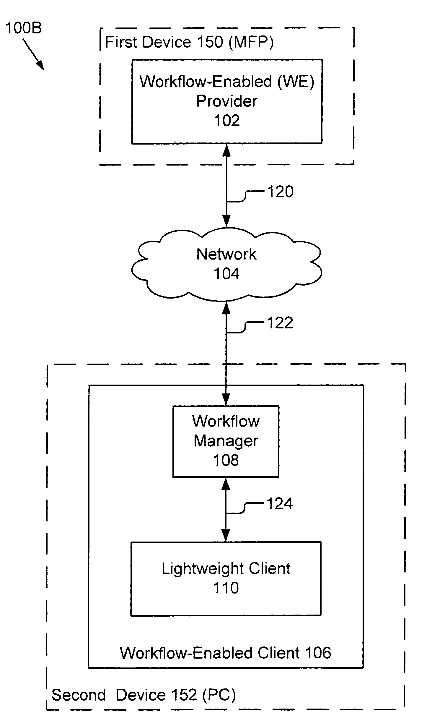
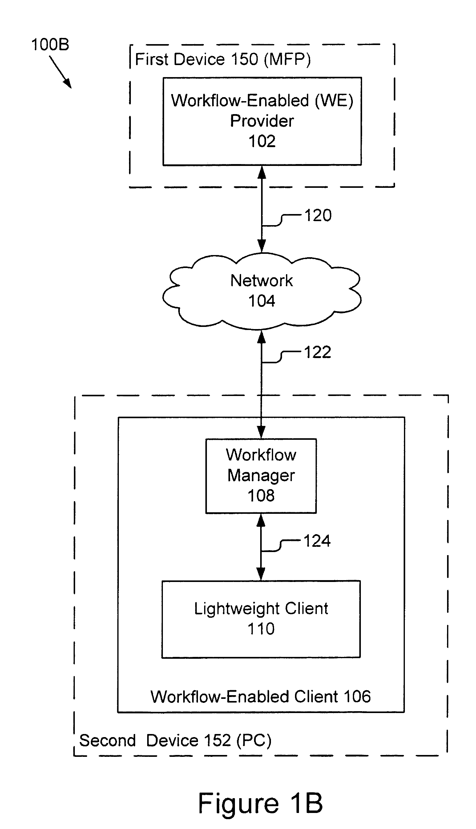
[0053]FIG. 1B shows the first and preferred configuration of the second embodiment for the distributed workflow-enabled system 100B in which the components of the system 100B are software operational on multiple devices. In this first configuration, a first device 150, for example a MFP, includes the workflow-enabled provider 102 while the second device 152, for example a personal computer, includes the workflow-enabled client 106. The workflow-enabled client 106 further comprises a workflow manager 108 and a lightweight client 110. The workflow-enabled provider 102 is coupled by signal line 120 to the network 104. The workflow-enabled client 106, in particular the workflow manager 108, is coupled by signal line 122 to the network 104. The workflow manager 108 is in turn coupled for communication by signal line 124 to the lightweight client 110. The workflow-enabled client 106 is operational on the personal computer. Although only a single lightweight client 110 is shown, those skil...

third embodiment

[0058]FIG. 2 is a block diagram of a complex distributed workflow-enabled system 200 configured in accordance with the present invention. FIG. 2 illustrates yet another embodiment of the distributed workflow-enabled system 200 where there are multiple workflow-enabled providers 102a-102n and multiple workflow-enabled clients 106a-106n.

[0059]As shown in FIG. 2, the network 104 is coupled by signal lines 120 to a plurality of workflow-enabled providers 102a-102n. In one embodiment, the present invention may be implemented as software that may be installed onto a plurality of conventional provider devices. In another embodiment, the present invention is implemented as hardware that is built into the plurality of conventional provider devices. Once such devices have been enabled with the software of the present invention, they become workflow-enabled providers 102a-102n. The plurality of workflow-enabled providers 102a-102n in this embodiment includes: a workflow-enabled printer 102a, ...


PUM


Abstract

A workflow-enabled provider includes a service provider and a workflow manager interface unit. The workflow manager interface unit couples the service provider to a workflow manager to provide the automatic discovering, distributed processing and dynamic user interface generating functionality. An advertisement monitor listens for broadcasts from the workflow manager regarding new clients. A request module and a response module handle the transfer of data and control signals between the workflow manager and the service provider. A process control module performs a plurality of processing functions including aggregating requests from clients, selecting requests it can service, presenting user interfaces, processing input via the service provider and controlling the service provider. The user interface module is coupled to the process control module and dynamically generates user interfaces for display by the service provider.

Description

CROSS REFERENCE TO RELATED APPLICATIONS[0001]This application claims priority under 35 U.S.C. §119(e) from U.S. Provisional Patent Application No. 60 / 972,562, titled “Distributed Workflow Enabled System,” filed Sep. 14, 2007, which is incorporated by reference herein in its entirety.BACKGROUND OF THE INVENTION[0002]The present invention relates to distributed computing systems. More particularly, the present invention relates to systems and methods for distributing processing between provider devices and client devices. Still more particularly, the present invention relates to distributed workflow-enabled systems that provide automatic discovery, that provide a pre-define interface among providers and clients, that is customizable by the user, and that allocates processing between providers and clients.[0003]A variety of peripheral devices that each provides a specific function is common for most office environments. For example, most offices include one or more of the following off...

Claims


Application Information

Patent Timeline
IPC IPC(8): G06F15/16G06F21/31
CPCG06Q10/06
Inventor MCFARLAND, MAX E.PHILLIPS, DAJAMARIOTTI, ANDREAYU, HAIXIAGRIFFIN, MICHAEL G.E.RHODES, BRADLEYCHEMISHKIAN, SERGEYSCHWARTZ, EDWARD L.CASE, PATTYSAVITZKY, STEPHEN R.WOLFF, GREGORY J.
Owner RICOH KK
Why Eureka
Try Eureka