Method and apparatus for operating a fuel flexible furnace to reduce pollutants in emissions

a flexible furnace and furnace technology, applied in the field of furnace operations, can solve the problems of high cost, emissions reductions not achieving their full entitlement, preprocessing fuels, etc., and achieve the effect of reducing pollutant emissions

Active Publication Date: 2009-03-26
GENERAL ELECTRIC CO
View PDF12 Cites 40 Cited by
  • Summary
  • Abstract
  • Description
  • Claims
  • Application Information

AI Technical Summary

Benefits of technology

[0006]In accordance with another aspect of the invention, a fuel flexible furnace of a boiler to reduce pollutant emissions is provided that comprises a main combustion zone, a reburn zone downstream from the main combustion zone, a delivery system operably coupled to supplies of biomass and coal and configured to deliver the biomass and the coal as ingredients of first and reburn fuels to the main combustion zone and the reburn zone, with each fuel including flexible quantities of the biomass and/or the coal, the flexible quantities being variable with the furnace in an operating condition, a bu

Problems solved by technology

However, each of the above noted methods includes certain shortcomings that have limited their applicability.
These shortcomings include the need to rely on the availability of seasonal fuels, the need to preprocess the fuels, inefficiencies,

Method used


Image

  • Method and apparatus for operating a fuel flexible furnace to reduce pollutants in emissions
  • Method and apparatus for operating a fuel flexible furnace to reduce pollutants in emissions
  • Method and apparatus for operating a fuel flexible furnace to reduce pollutants in emissions

Examples


Embodiment Construction

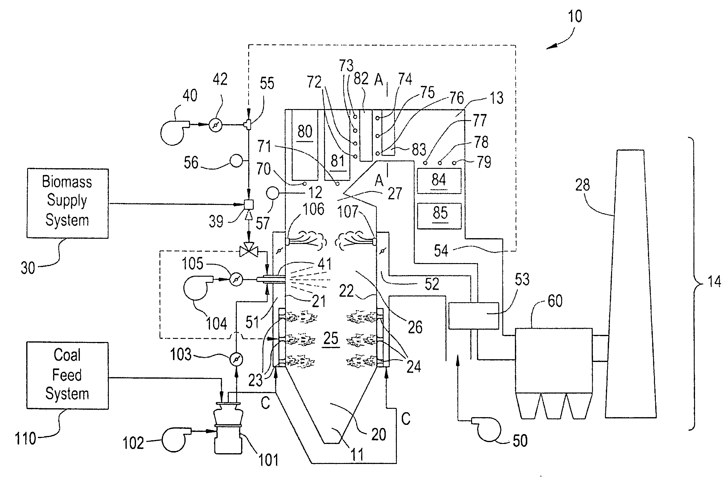
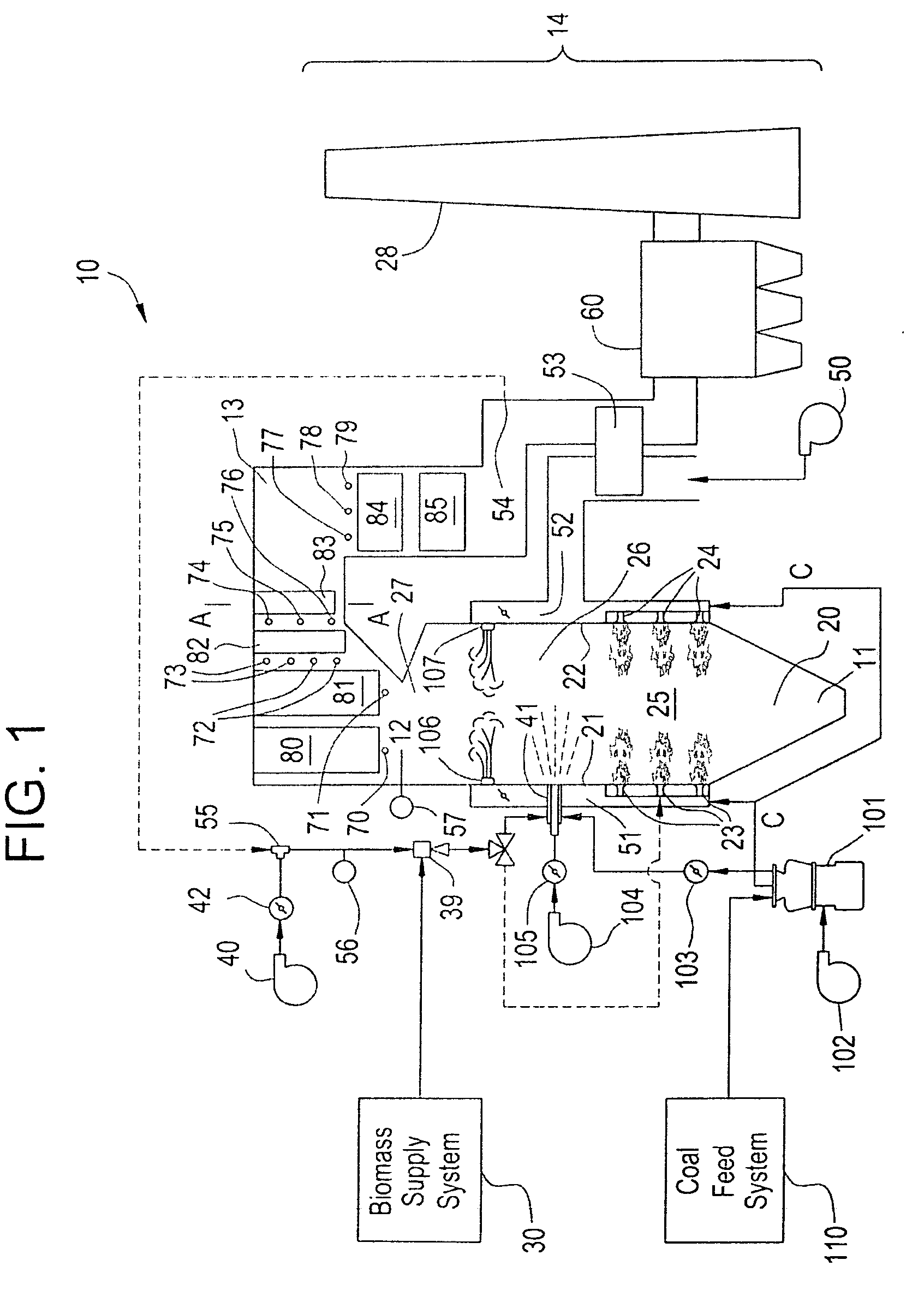
[0015]As shown in FIG. 1, a boiler 10 includes a furnace 20 having a furnace bottom 11, an outlet 12, an exhaust path 13 and an exhaust system 14. The outlet 12 is typically narrower than the furnace 20 and is provided to allow emissions generated in the furnace to escape. The exhaust path 13, through which the emissions travel upon exiting through the outlet 12, is coupled to the outlet 12 and extends first in a substantially lateral orientation with respect to the furnace 20 and then in a substantially downward orientation with respect to the furnace 20. Accumulated particulate matter from emissions generated in the furnace 20 is removed from heat transfer surfaces in the exhaust path 13. The exhaust system 14 is coupled to the exhaust path 13 and allows the emissions generated in the furnace 20 to be exhausted to the atmosphere. While the boiler 10 is illustrated as a pulverized coal (PC) opposed wall-fired boiler, embodiments of this invention could be applied to other types of ...


PUM


Abstract

A fuel flexible furnace, including a main combustion zone, a reburn zone downstream from the main combustion zone, and a delivery system operably coupled to supplies of biomass and coal and configured to deliver the biomass and the coal as ingredients of first and reburn fuels to the main combustion zone and the reburn zone, with each fuel including flexible quantities of the biomass and/or the coal. The flexible quantities are variable with the furnace in an operating condition.

Description

CROSS REFERENCE TO RELATED APPLICATIONS[0001]This non-provisional application claims the benefit of priority of U.S. Provisional Application 60 / 999,749, which was converted on Oct. 11, 2007 to provisional status from U.S. patent application Ser. No. 11 / 860,222, filed on Sep. 24, 2007, the contents of both of which are incorporated herein in their entirety.BACKGROUND OF THE INVENTION[0002]Aspects of the present invention relate to furnace operations and, more particularly, to furnace operations that reduce pollutants in emissions.[0003]As global climate concerns grow, methods and apparatuses for reducing emissions from fossil fuel boilers have been employed. These methods and apparatuses have incorporated fuel staging, biomass co-firing, biomass gasification, biomass reburn and / or combinations thereof into furnace operations to reduce pollutant emissions including NOx, SOx, CO2, Hg, etc.[0004]However, each of the above noted methods includes certain shortcomings that have limited the...

Claims


Application Information

Patent Timeline
IPC IPC(8): F23B10/00
CPCF23C1/00F23C2201/301F23G2201/70F23C2900/01001
Inventor EITENEER, BORIS NIKOLAEVICHSEEKER, WILLIAM RANDALLPAYNE, ROY
Owner GENERAL ELECTRIC CO
Why Eureka
Try Eureka