Sluice assembly for separating heavy particles from slurry

a technology of heavy particles and sluice assemblies, which is applied in the direction of solid separation, gas current separation, sorting, etc., can solve the problems of limited number of known plastics that can be employed, and achieve the effects of low maintenance, efficient collection of precious minerals, and low cost of manufactur

Inactive Publication Date: 2009-03-26
RAINWATER CHUCK +1
View PDF35 Cites 14 Cited by
  • Summary
  • Abstract
  • Description
  • Claims
  • Application Information

AI Technical Summary

Benefits of technology

[0015]Moreover, the “V” shaped diverters preferably include an opening at their narrow ends for allowing heavier materials to pass through the diverter to additional “V” shaped diverters. Preferably, the lower sluice box deck also includes one or more holes positioned immediately downstream of the “V” shaped riffles so that heavier particles which are diverted by the “V” shaped diverters then pass through the holes for collection. Preferably, the riffles forming the “V” shaped diverters have a height sufficient to divert particles having a predetermined specific gravity or greater toward and into the deck holes for collection. Also preferably, the riffles are sufficiently low so that lighter particles within the slurry can pass over the riffles so as to not be diverted by the “V” shaped diverters and thus avoid collection.
[0019]Thus, it is an object of the present invention to provide a sluice assembly which more efficiently collects precious minerals and gemstones than prior sluice assemblies.
[0020]It is still an additional object of the invention to provide a sluice assembly which is lightweight.
[0021]Moreover, it is an object of the present invention to provide a sluice assembly that is inexpensive to manufacture, requires little maintenance, and is easy to operate.

Problems solved by technology

Only a limited number of known plastics can be employed as sluice decks which would conform with these hardness and frictional properties.

Method used


Image

  • Sluice assembly for separating heavy particles from slurry
  • Sluice assembly for separating heavy particles from slurry
  • Sluice assembly for separating heavy particles from slurry

Examples


Embodiment Construction

[0037]While the present invention is susceptible of embodiment in various forms, as shown in the drawings, hereinafter will be described the presently preferred embodiments of the invention with the understanding that the present disclosure is to be considered as an exemplification of the invention and it is not intended to limit the invention to specific embodiments illustrated.

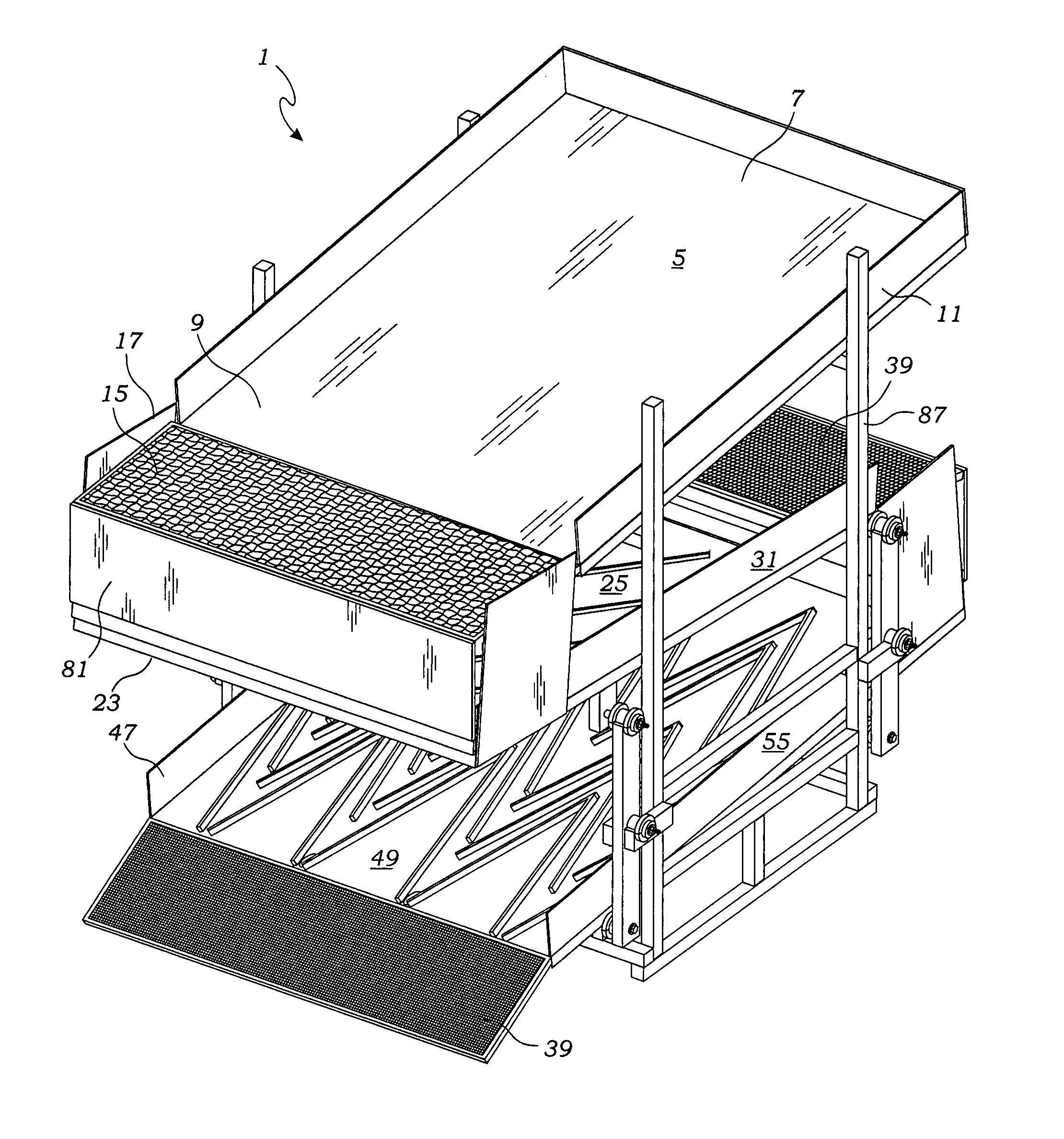
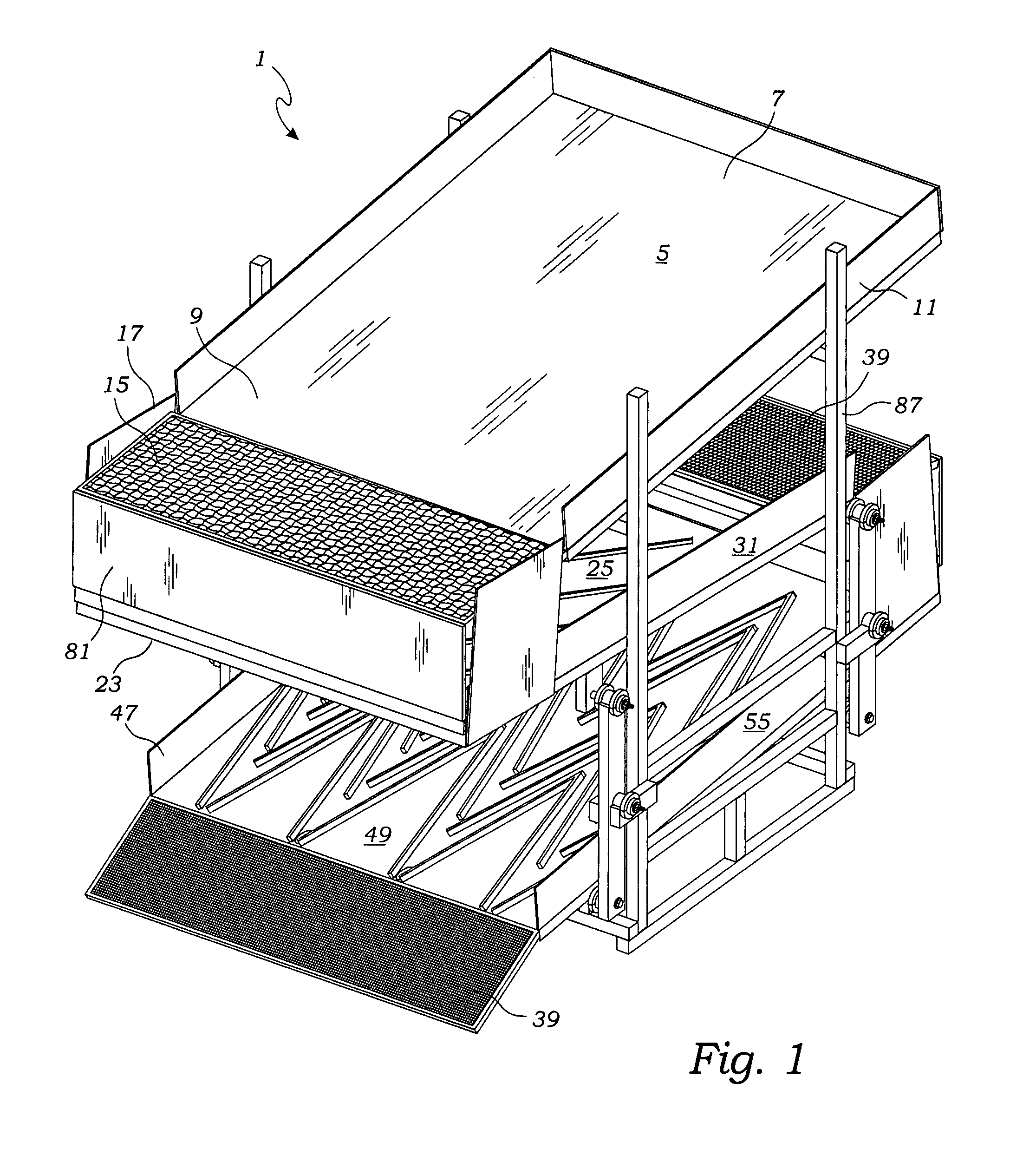
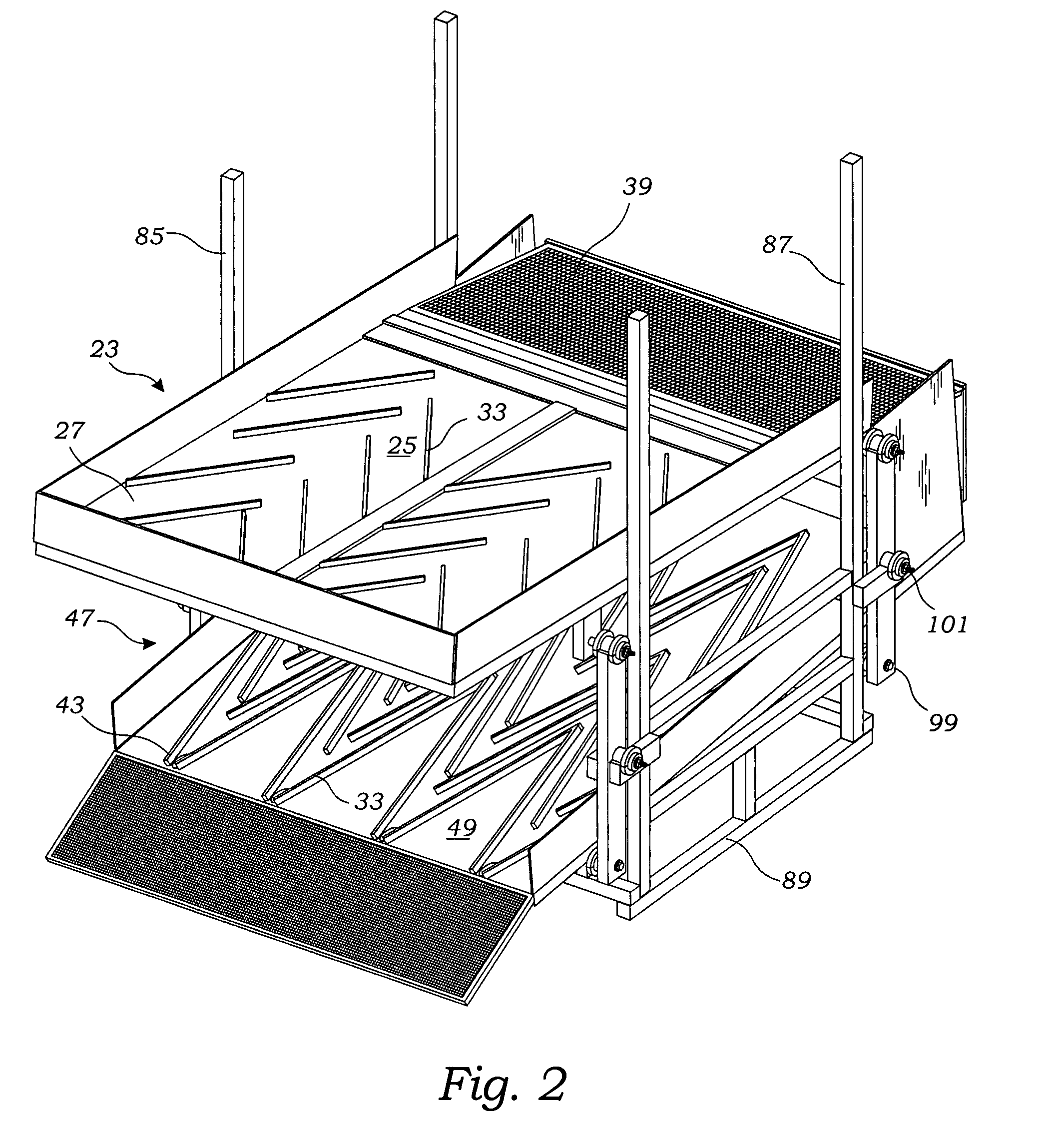
[0038]With reference to the figures, the sluice assembly 1 of the present invention includes at least one sluice box, and preferably includes two sluice boxes referred to herein as a top sluice box 23 and a bottom sluice box 47. The top sluice box 23 includes a sloping deck 25 defining an upstream end 27 and a downstream end 29. Preferably, the sluice box further includes sidewalls 31 as well as riffles 33. Similarly, the bottom sluice box 47 includes a sloping bottom deck 49 defining an upstream end 51 and a downstream end 53. As shown, the bottom sluice box further includes sidewalls 55 as well as riffles ...


PUM


Abstract

A sluice assembly for separating heavy particles from slurry is provided. The sluice assembly includes one or more sluice boxes having decks made of plastic having a Shore D hardness between 50-75, a static coefficient of friction less than 0.3 and a kinetic coefficient of friction less than 0.2. In a preferred embodiment, the sluice assembly includes a pair of sluice boxes in which a top sluice box is positioned above the bottom sluice box so that slurry flowing from the downstream end of the first sluice box is received by the upstream end of the bottom sluice box. The bottom deck includes tapered riffles which are arranged to provide “V” shaped diverters for diverting heavier particles for collection. The sluice box upper deck may include laterally extending riffles for collection of heavier particles.

Description

BACKGROUND OF THE INVENTION[0001]The present invention relates to mineral and gemstone mining. More particularly, the present invention relates to sluice assemblies for recovering precious metal deposits and gemstones from a slurry mixture of water and mineral ore.[0002]Wet placer mining has been employed for centuries for separating metals, particularly gold, platinum, and gemstones from rock and sand constituents. Conventionally, various apparatus are utilized for concentrating or separating mineral or gemstone containing materials. The most basic construction includes the use of a gold pan. In use, a slurry mixture is placed in the gold pan and a mixture of gravity, agitation and flotation is employed to cause heavier gold particles to sink to the bottom of the pan while lighter materials are caused to flow out of the pan. Since the pan is typically handled manually, its size limits the amount of material that can be processed. Furthermore, panning is a tedious and manually stren...

Claims


Application Information

Patent Timeline
Patent Type & Authority Applications(United States)
IPC IPC(8): B07B9/00
CPCB03B5/26
Inventor RAINWATER, CHUCKRAINWATER, MATTHEW
Owner RAINWATER CHUCK
Why Eureka
Try Eureka