Contact-less smart card reader

a technology of contactless and smart cards, applied in the field of contactless smart card readers, can solve the problems of not explicitly addressing the issue of improving readability, unable to address the aforesaid issue, and unable to capture so as to increase the signal to noise ratio in the reader, and facilitate the capture of maximum number of flux lines.

Inactive Publication Date: 2009-03-26
SCOLIS TECHNOLOGIES (INDIA) PVT LTD
View PDF6 Cites 2 Cited by
  • Summary
  • Abstract
  • Description
  • Claims
  • Application Information

AI Technical Summary

Benefits of technology

[0009]Accordingly, embodiments of the present invention provide an improved contact-less smart card reader including at least one separate transmit antenna and at least one separate receive antenna for transmitting and receiving respectively, wherein the antenna geometry of said reader is adapted to capture maximum number of flux lines that pass through the corresponding smart card and minimum number of flux lines that do not pass though the corresponding smartcard, thereby increasing the signal to noise ratio in the reader and consequently, increasing the strength of the signal qualities received from the smart card, particularly in the event of operation of said smart card from a substantial operating distance. Preferred embodiments of the contact-less smart card reader of the present invention can include one or more of the following features.
[0010]The receive coil of the receive antenna can be adapted to have a geometrical shape to capture maximum number of flux lines that pass through the card and minimum number of flux lines that do not pass though the card.
[0018]Embodiments of the present invention can also provide a contact-less smart card system including at least one contact-less smart card having improved performance and higher operating distance and operatively coupled to at least one improved contact-less smart card reader having improved antenna geometry. Preferred embodiments of the contact-less smart card reader system of the present invention can include one or more of the following features.
[0021]Embodiments of the present invention can also provide a method for assembling an improved smart card reader that includes providing and operatively connecting a processor, a memory, a reader IC, a matching circuit and at least one separate transmit antenna and at least one separate receive antenna for transmitting and receiving respectively, wherein the method comprises designing the antenna geometry of the reader so as to facilitate capturing maximum number of flux lines that pass through the corresponding smart card and minimum number of flux lines that do not pass though the corresponding smart card thereby increasing the signal to noise ratio in the reader and consequently, increasing the strength of the signal quality received from the smart card, particularly in the event of operation of said smart card from a substantial operating distance.
[0022]In accordance with a preferred embodiment of the method for assembling an improved smart card reader of the present invention can further comprise designing the receive coil of the receive antenna to a geometrical shape for facilitating capturing maximum number of flux lines that pass through the card and minimum number of flux lines that do not pass through the card.

Problems solved by technology

However, the deficiencies in geometry and structure of the antenna in the corresponding reader result in receipt of feeble signal qualities from the card by the reader thereby causing hindrance to reading of the card from a substantial operating distance.
Heretofore, no one has explicitly addressed the issue of improving the readability of a contact-less smart card reader by increasing the received signal strength, particularly when reading of the card is required to be performed from a substantial operating distance.
This application therefore does not address the aforesaid issue.
Hence, none of the aforesaid prior art documents address the issue of improving the readability of contact-less smart card reader by increasing the received signal strength, particularly when reading of the card is required to be performed from a substantial operating distance

Method used


Image

  • Contact-less smart card reader
  • Contact-less smart card reader
  • Contact-less smart card reader

Examples


Embodiment Construction

[0028]The following includes description of particular embodiments of the present invention, which is purely for the sake of understanding and not by way of any sort of limitation.

[0029]As stated aforesaid, the present invention primarily aims at increasing the signal qualities received from a smart card by improving the antenna geometry of the smart card reader. This technical advancement was hitherto unknown and not conceived by persons skilled in the art.

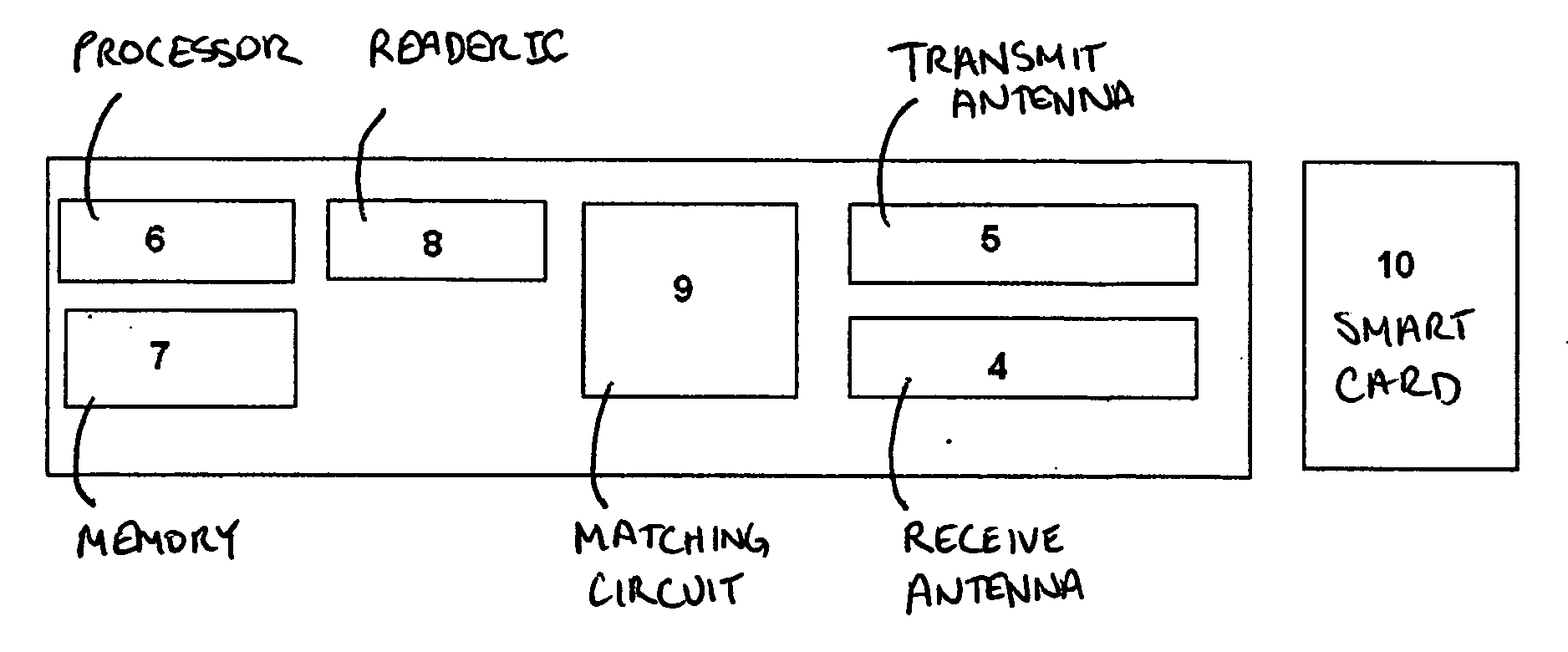
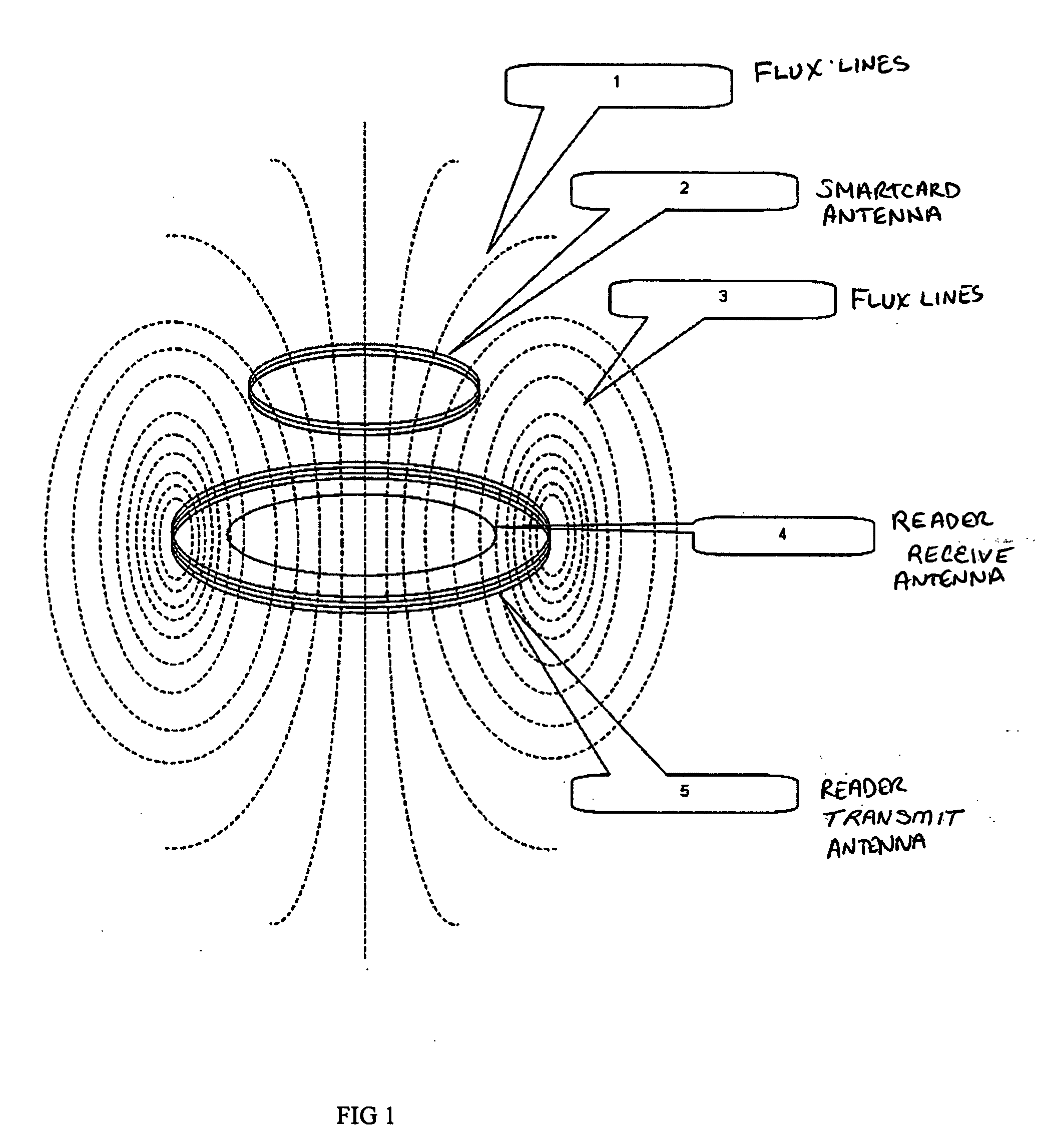
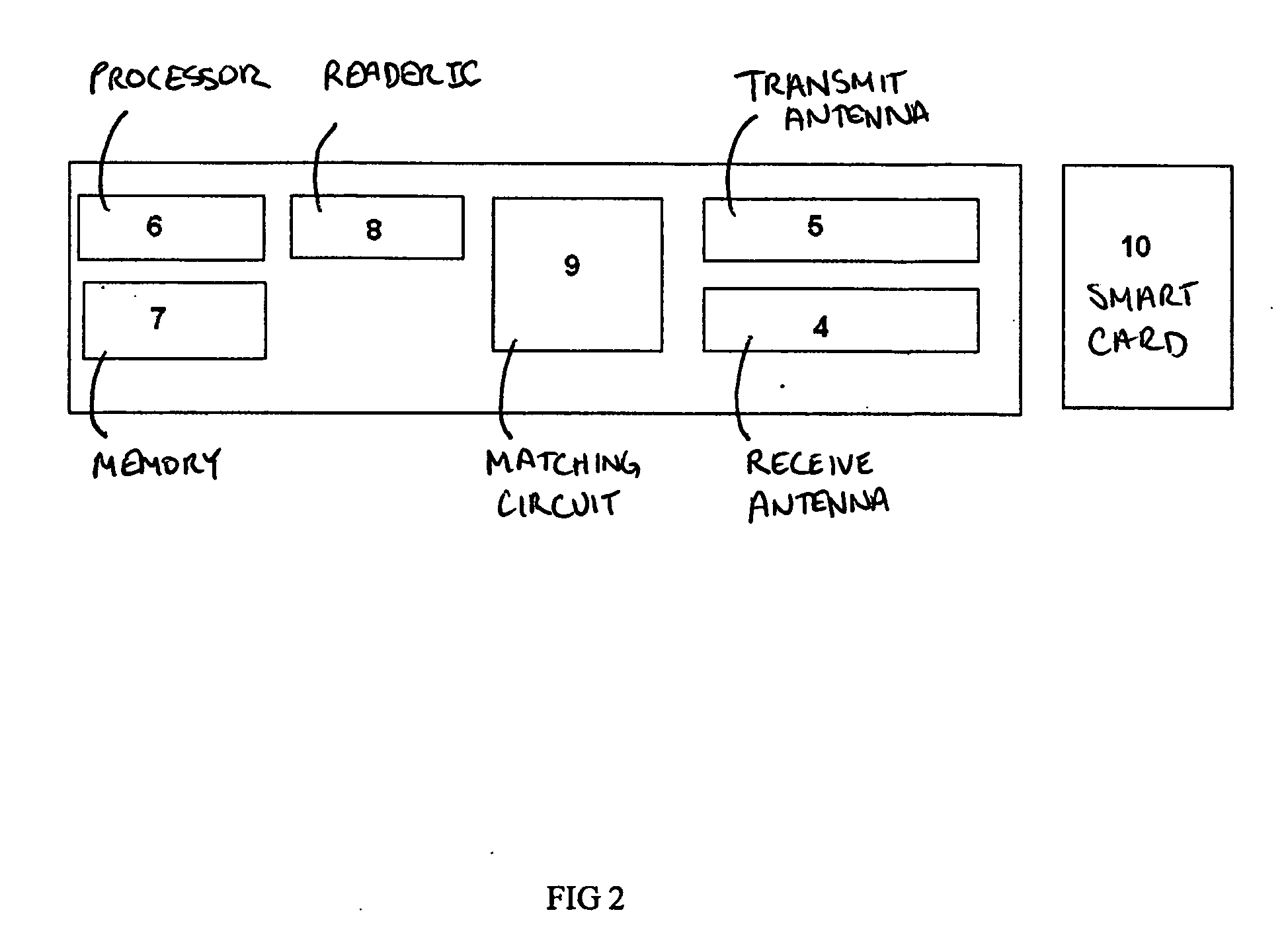
[0030]From FIG. 1 and the foregoing description it ought to be clear that the card sends data to the reader by means of load modulation on the carrier. When the card does load modulation, the total number of flux lines that pass through the transmitting antenna of the reader changes. This change in number of flux lines is recognized by the reader as change in voltage and this is used to receive data from the contact-less smart card.

[0031]Similarly, when the card does load modulation, the total number of flux lines that pass throu...


PUM


Abstract

An improved contact-less smart card reader is disclosed that includes at least one separate transmit antenna and at least one separate receive antenna for transmitting and receiving respectively, wherein the antenna geometry of said reader is adapted to capture a maximum number of flux lines that pass through the corresponding smartcard and a minimum number of flux lines that do not pass though the corresponding smartcard, thereby increasing the signal to noise ratio in the reader and consequently, increasing the strength of the signal qualities received from the smart card, particularly in the event of operation of the smart card from a substantial operating distance. A method is also provided for assembling an improved contact-less smartcard reader as described above.

Description

RELATED APPLICATIONS[0001]This application claims priority under 35 U.S.C. § 119 or 365 to Indian Patent Application No. 2118 / CHE / 2007, filed on May 8, 2008, which claims priority to Indian Provisional Patent Application No. 2118 / CHE / 2007, filed on Sep. 20, 2007. The entire teachings of the above applications are incorporated herein by reference.FIELD OF THE INVENTION[0002]The present invention, in general, relates to an improved contact-less smart card reader, and in particular, to a contact-less smart card reader having improved antenna geometry, whereby signal to noise ratio in the reader is increased and consequently the strength and quality of a signal received from a contact-less smart card are increased.BACKGROUND OF THE INVENTION[0003]Conventional contact-less smart card readers are made up of reader silicon, passive filter circuits and antenna. Smart cards can operate over 13.56 MHz RF frequency based on the ISO14443 or ISO15693 or ISO18000-3 standard, for example. The smar...

Claims


Application Information

Patent Timeline
Patent Type & Authority Applications(United States)
IPC IPC(8): G06K7/10
CPCG06K7/10346G06K7/10316
Inventor BALASUBRAMANIAN, DURAIPANDIANADAR
Owner SCOLIS TECHNOLOGIES (INDIA) PVT LTD
Why Eureka
Try Eureka