
Multiple Configuration Image Scanner

a scanner and configuration technology, applied in the field of image-based bar code readers, can solve the problems of one or more frame delays and the difficulty of predicting the timing of register updates

Inactive Publication Date: 2009-03-26
SYMBOL TECH INC
View PDF2 Cites 22 Cited by
  • Summary
  • Abstract
  • Description
  • Claims
  • Application Information

AI Technical Summary

Benefits of technology

[0007]An exemplary system has an image sensor that includes multiple configuration registers. With multiple configuration registers a video mode can be implemented where the video consists of a continuous sequence of frames with a fixed sequence of a number of configurations. The configurations can vary the frame size, exposure time, gain, etc. Compared to a sensor with only one set of configuration registers, successive frames can be captured with different configurations without synchronization issues or frame lag.

Problems solved by technology

If multiple configurations are desired, then the configuration registers must be reprogrammed during an image capture sequence and there is typically one or more frame delays before an image with the updated configuration is produced.
This presents a synchronization issue because the timing of the register updates may be difficult to predict.

Method used


Image

  • Multiple Configuration Image Scanner
  • Multiple Configuration Image Scanner
  • Multiple Configuration Image Scanner

Examples


Embodiment Construction

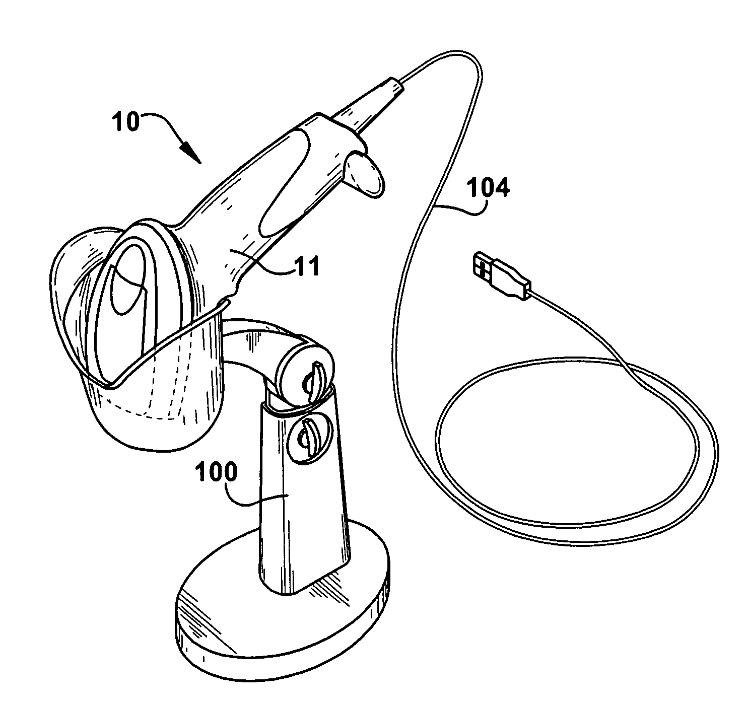
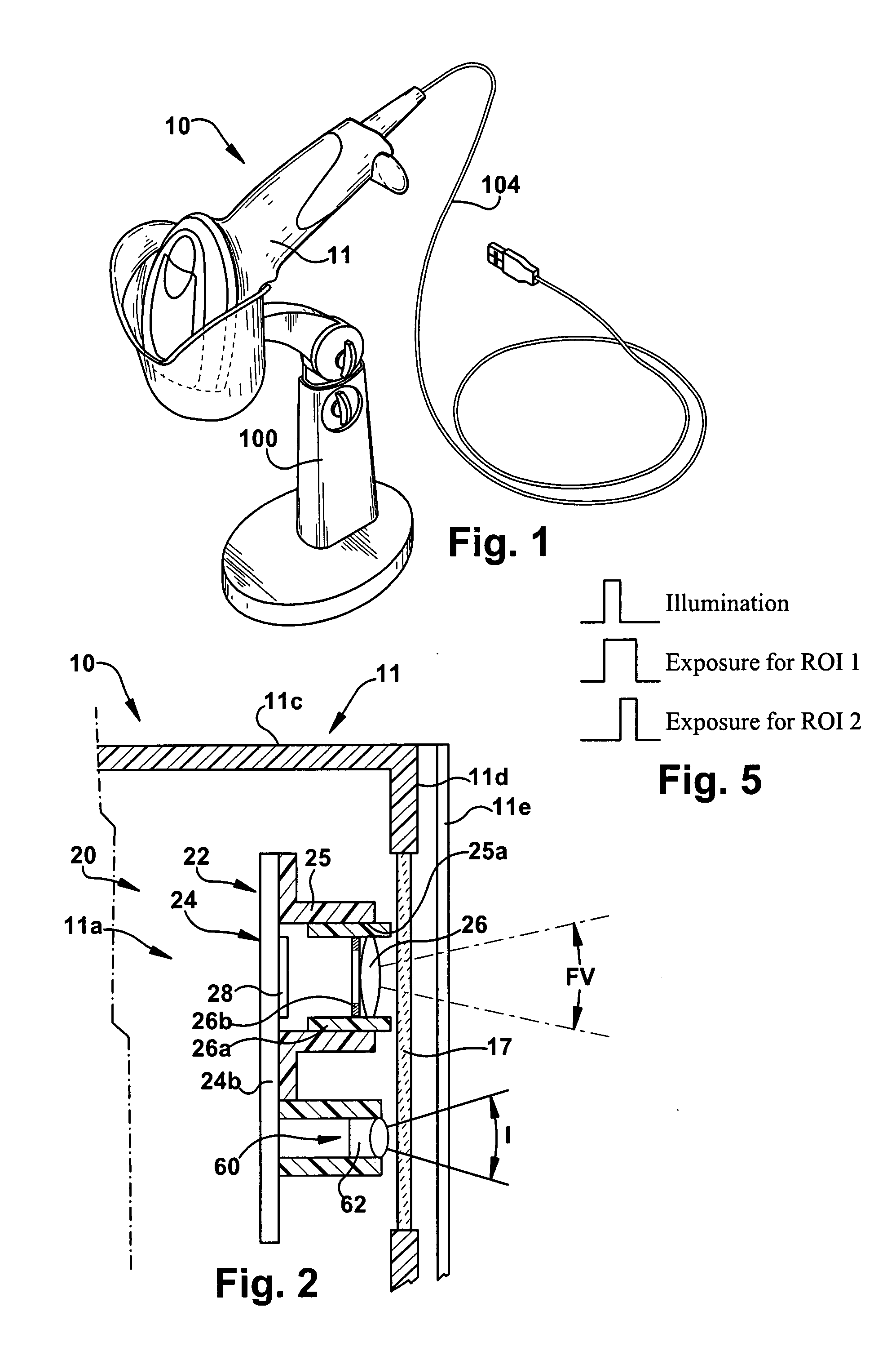
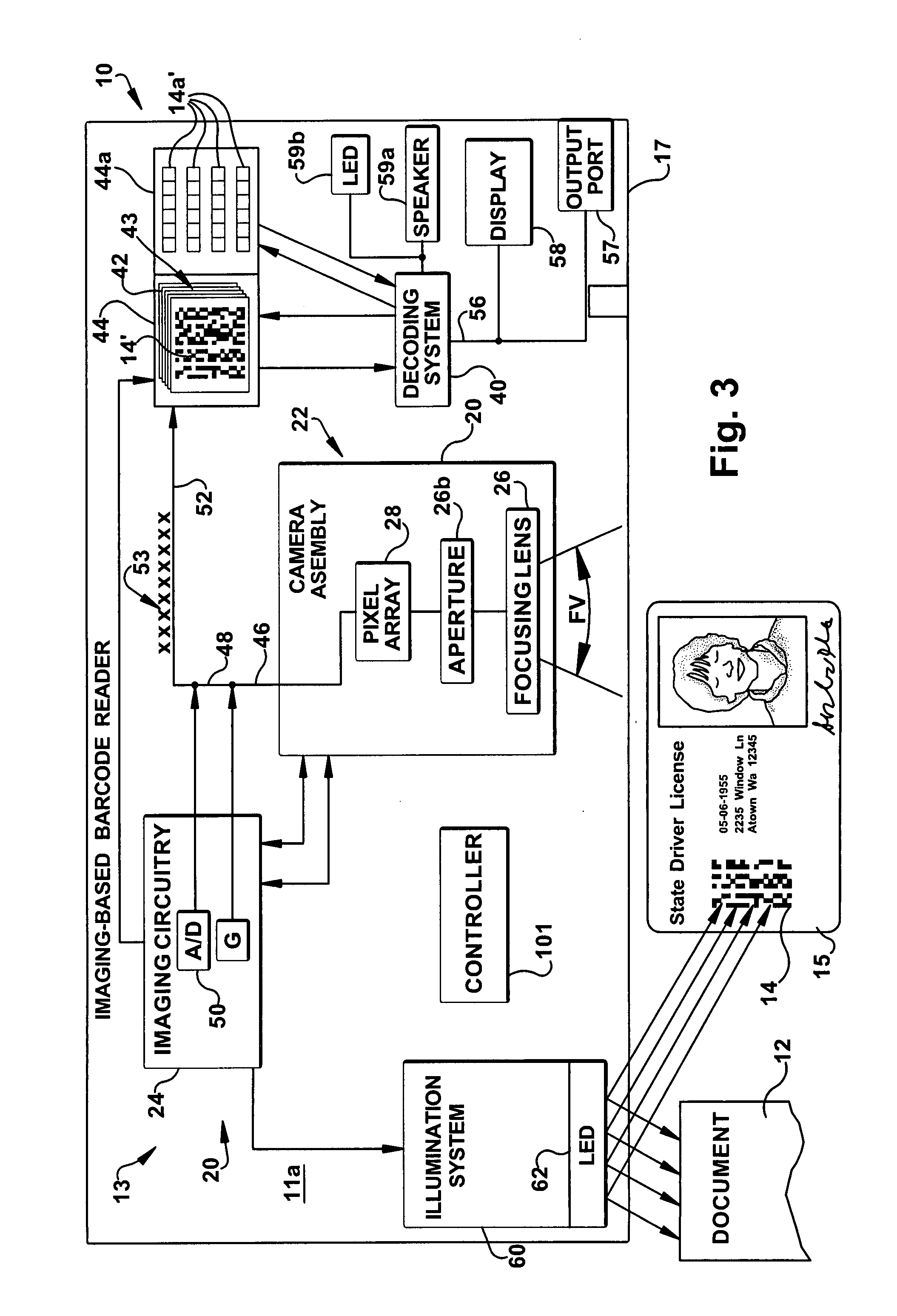
[0015]An imaging-based scanner or reader that is capable of reading bar codes is shown schematically at 10 in the Figures. One example of a 2D bar code 14 is shown in FIG. 3. Additionally, the reader 10 is also capable of capturing images such as an image of a document 12. The bar code reader 10 includes a housing 11 supporting an imaging system 20 and a decoding system 40 (FIG. 3). The housing 11 supports a transparent window 17 through which reflected illumination from the target document is received by the imaging system 20.

[0016]When enabled, the imaging system 20 captures an image frame 42 of a field of view FV of the imaging system which is stored in a memory 44. The imaging process captures an image of the target bar code. The decoding system 40 analyzes a captured image frame 42 and attempts to decode decodable portions of the image frame 42. The decoded portions of the image frame 42 are stored in a buffer memory 44a. Alternately, a series of image frames 43 are captured an...


PUM


Abstract

An imaging-based bar code reader that includes an imaging and decoding system. Focusing optics and a sensor array define a field of view. An exemplary system has an image sensor includes multiple configuration registers. With multiple configuration registers a video mode can be implemented where the video consists of a continuous sequence of frames with a fixed sequence a number of configurations. The configurations can vary the frame size, exposure time, gain, etc. Compared to a sensor with only one set of configuration registers, successive frames can be captured with different configurations without synchronization issues or frame lag.

Description

FIELD OF THE INVENTION[0001]The present invention relates to an imaging-based bar code reader and, more particularly, to a bar code reader that facilitates capturing images.BACKGROUND OF THE INVENTION[0002]Various electro-optical systems have been developed for reading optical indicia, such as bar codes. A bar code is a coded pattern of graphical indicia comprised of a series of bars and spaces having differing light reflecting characteristics. The pattern of the bars and spaces encode information. In certain bar codes, there is a single row of bars and spaces, typically of varying widths. Such bar codes are referred to as one dimensional (1D) bar codes. Other bar codes include multiple rows of bars and spaces, each row typically having the same width. Such bar codes are referred to as two dimensional (2D) bar codes.[0003]Imaging systems include charge coupled device (CCD) arrays, complementary metal oxide semiconductor (CMOS) arrays, or other imaging pixel arrays having a plurality...

Claims


Application Information

Patent Timeline
IPC IPC(8): G06K7/10
CPCG06K7/10722G06K7/1093G06K7/10851G06K7/10841
Inventor CARLSON, BRADLEY S.HE, DUANFENG
Owner SYMBOL TECH INC
Learn More