
Electric joystick mechanism for an ophthalmic apparatus

a technology of electric joystick and ophthalmology, which is applied in the direction of mechanical control devices, manual control with single controlling member, applications, etc., can solve the problems of difficulty in performing fine angle adjustment of joystick, examination unit could unintentionally move at a speed, and takes time and effort for the examiner, so as to improve the manipulation performance of joystick and simple structure

Inactive Publication Date: 2009-03-26
NIDEK CO LTD
View PDF5 Cites 34 Cited by
  • Summary
  • Abstract
  • Description
  • Claims
  • Application Information

AI Technical Summary

Benefits of technology

[0008]An object of the invention is to overcome the problems described above and to provide an ophthalmic apparatus comprising an electric joystick mechanism which is capable of improving manipulation performance of a joystick, and is simple in structure.

Problems solved by technology

However, in the apparatus disclosed in Japanese Patent Application Unexamined Publication No. 2002-369799, fine angle adjustment of the joystick is difficult to be performed, and the examination unit could unintentionally move at a speed which is against the examiner's intention when the velocity control is performed in the range of the tilting angle of the joystick which is beyond the predetermined angle.
In addition, it is necessary to largely tilt (e.g., at 35 degrees) the joystick in order to move the examination unit quickly, which takes time and effort for the examiner.
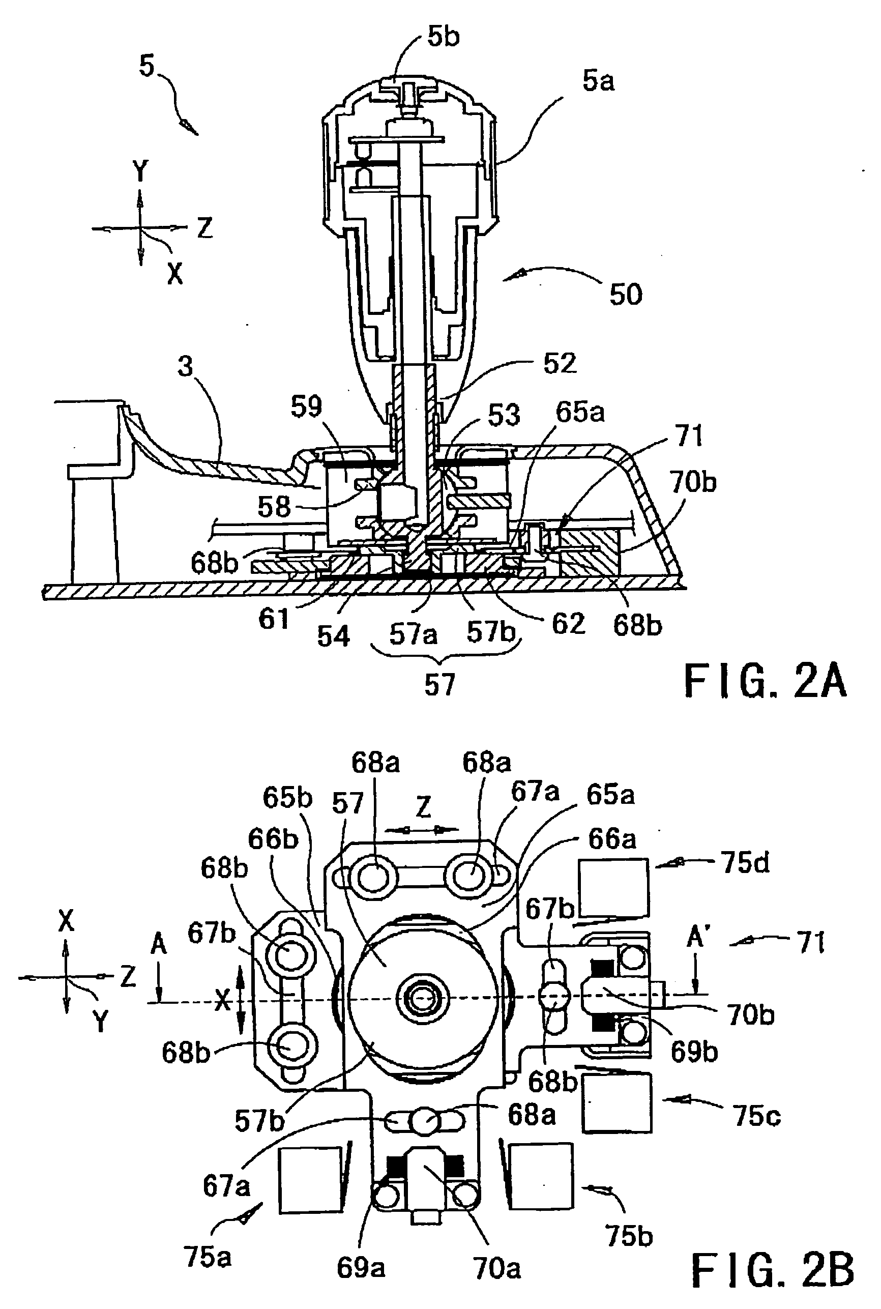
In addition, the joystick mechanism disclosed in Japanese Patent Application Unexamined Publication No. 2002-369799 is complicated in structure as a whole because the rotation shafts which are different in shape need to be prepared (in the vicinities of connections with the joystick) in order to convert the tilting movement of the joystick into the rotation movement of the rotation shafts in the back / forth direction and in the right / left direction.

Method used


Image

  • Electric joystick mechanism for an ophthalmic apparatus
  • Electric joystick mechanism for an ophthalmic apparatus
  • Electric joystick mechanism for an ophthalmic apparatus

Examples


Embodiment Construction

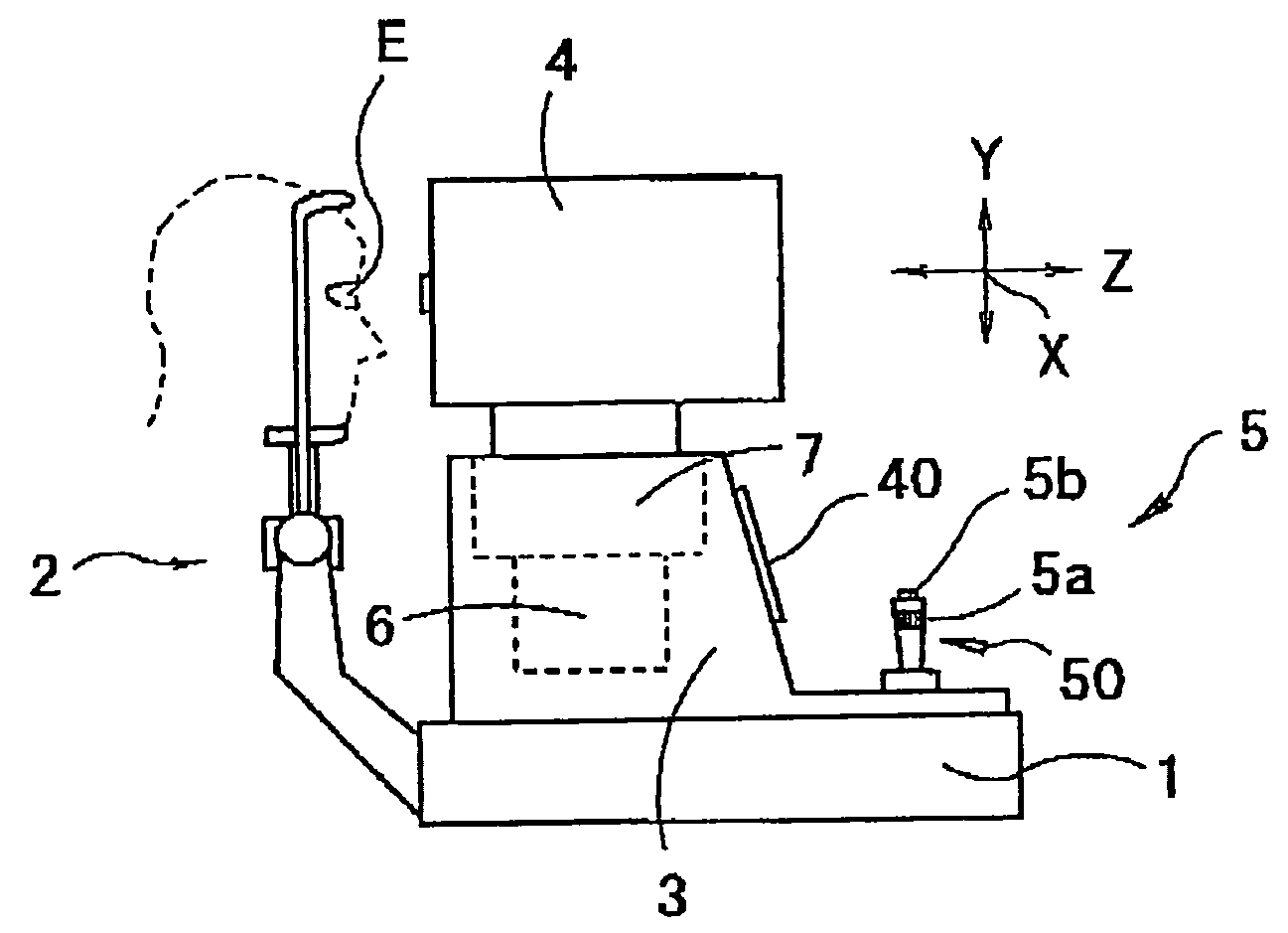
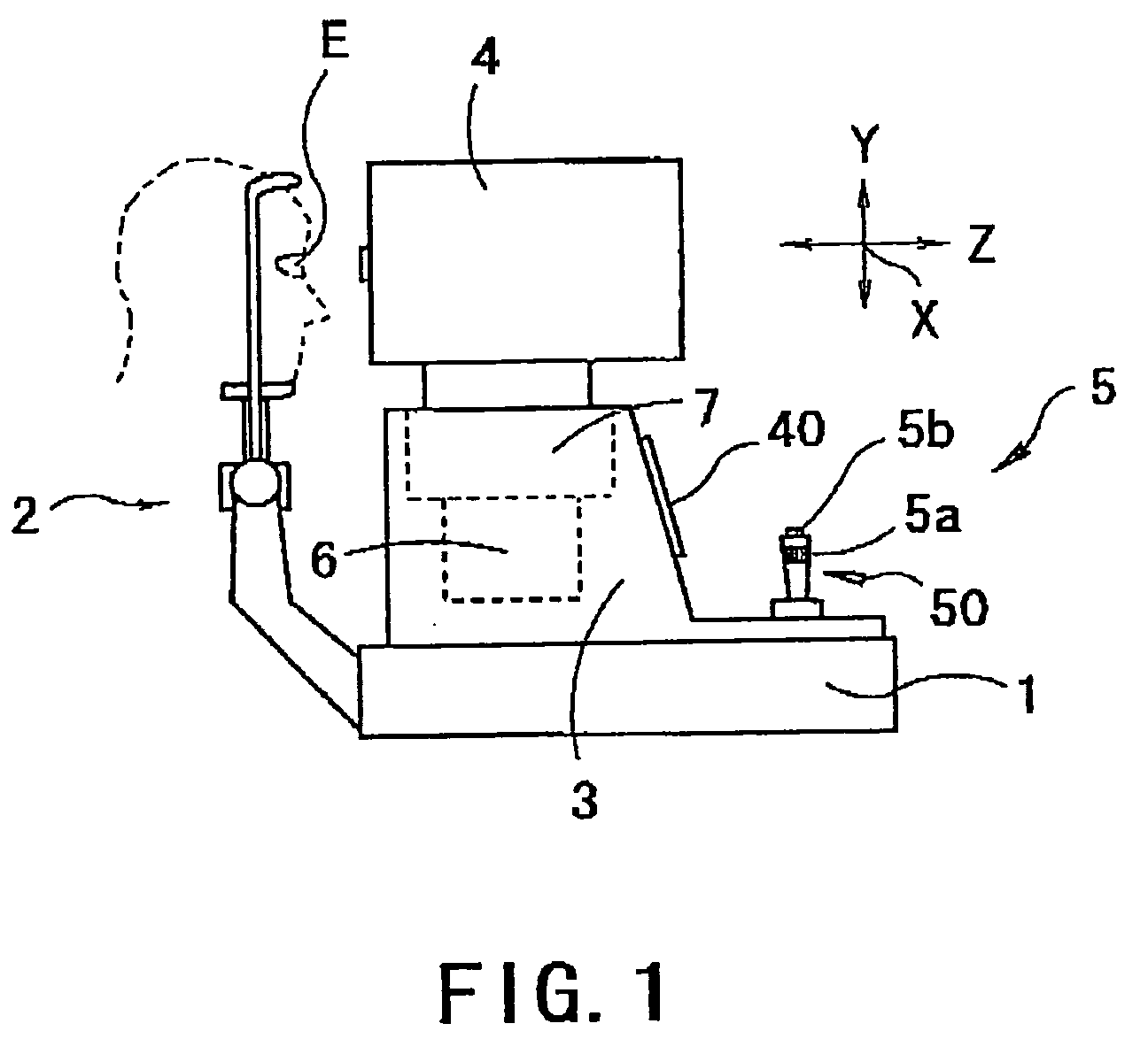
[0016]A detailed description of an electric joystick mechanism for an ophthalmic apparatus according to a preferred embodiment of the present invention is provided below with reference to the accompanying drawings. FIG. 1 is a schematic external view showing the ophthalmic apparatus comprising the joystick mechanism according to the preferred embodiment of the present invention. The ophthalmic apparatus is a stationary ophthalmic apparatus comprising a base 1, a face supporting unit 2 attached to the base 1, main body 3 mounted on the base 1, a measurement unit (an ophthalmic examination unit) 4 which houses a measurement optical system (e.g., an eye refractive power measurement optical system) arranged to examine an examinee's eye E, and a joystick mechanism 5 which is operated in order to move the measurement unit 4.

[0017]The measurement unit 4 is moved in an up / down direction (a Y-direction shown in FIG. 1) with respect to the eye E by a Y driving unit 6 provided in the main body...


PUM


Abstract

An electric joystick mechanism for an ophthalmic apparatus which is capable of improving manipulation performance of a joystick and is simple in structure comprises a base, a joystick having a shaft, a driving unit having a motor for moving an ophthalmic examination unit horizontally, and a control unit for controlling the driving unit in response to tilting manipulation of the joystick by an examiner, wherein the control unit performs first control of finely moving the examination unit by controlling the driving unit based on a manipulation signal of the joystick, and second control of roughly moving the examination unit by controlling the driving unit when tilting condition of the joystick becomes a predetermined tilting condition, and in the second control, velocity of driving of the driving unit is controlled based on velocity of the tilting manipulation of the joystick in the first control.

Description

BACKGROUND OF THE INVENTION[0001]1. Field of the Invention[0002]The present invention relates to an electric joystick mechanism for an ophthalmic apparatus, which moves an ophthalmic examination unit horizontally.[0003]2. Description of Related Art[0004]In recent years, in an ophthalmic apparatus which requires alignment with respect to an examinee's eye (e.g., an auto refractometer, a fundus camera), such an apparatus that electrically detects manipulation of a joystick and a trackball by an examiner and electrically drives an ophthalmic examination unit having a measurement optical system and other elements based on a result of the detection is proposed (see Japanese Patent Application Unexamined Publication No. 2002-369799).[0005]In the apparatus disclosed in Japanese Patent Application Unexamined Publication No. 2002-369799, driving and control of the examination unit is divided into positional control and velocity control in accordance with a tilting angle of the joystick. In a...

Claims


Application Information

Patent Timeline
IPC IPC(8): A61B3/00
CPCA61B3/0033G05G2009/04744A61B3/028A61B3/0083
Inventor MIMURA, YOSHIAKI
Owner NIDEK CO LTD
Learn More