Parallax barrier, multiple display device and parallax barrier manufacturing method

a manufacturing method and display device technology, applied in the direction of optical elements, instruments, printing, etc., can solve the problems of difficult to obtain the extremely high accuracy of masks, uniform visibility of the entire screen for observers, etc., and achieve the effect of improving the entire screen visibility and limited accuracy

Inactive Publication Date: 2009-03-26
SHARP KK
View PDF4 Cites 16 Cited by
  • Summary
  • Abstract
  • Description
  • Claims
  • Application Information

AI Technical Summary

Benefits of technology

[0015]In order to overcome the problems described above, preferred embodiments of the present invention provide a parallax barrier used in a multiple display device, wherein the parallax barrier can improve the entire screen visibility and can be manufactured by a mask drawing technology that has limited accuracy.
[0020]Moreover, in the multiple display device including the image-producing device attached with the parallax barrier having the desired barrier pitch distance, the average pitch distance of the parallax barrier and the pixel pitch of the image-producing device preferably are set to different. As a result, it is possible to display to an observer an image having the uniform visibility over the entire screen.
[0022]With the above arrangement, by setting the first pitch to an easy to manufacture pitch distance that is closest to the desired pitch distance (which is desired based on design theory), viewing angle properties that are as ideal as possible can be obtained on the entire screen. Furthermore, the second pitches absorb barrier pitch errors that are caused by accumulated differences in pitch distance between the first pitches and the desired pitch. Therefore, it is possible to produce a parallax barrier wherein the barrier pitch error in total is substantially none.

Problems solved by technology

Therefore, the entire screen visibility for the observer is not uniform.
However, the conventional arrangements described above have the following difficulty in manufacturing the parallax barrier.
Therefore, it is difficult to obtain the mask having the necessary extremely high accuracy using a current mask drawing technology for liquid crystals.

Method used


Image

  • Parallax barrier, multiple display device and parallax barrier manufacturing method
  • Parallax barrier, multiple display device and parallax barrier manufacturing method
  • Parallax barrier, multiple display device and parallax barrier manufacturing method

Examples


Embodiment Construction

[0037]A preferred embodiment of the present invention is described below with reference to FIGS. 1 to 6. In this preferred embodiment, a liquid crystal display device is described as an example of a multiple display device of the present invention.

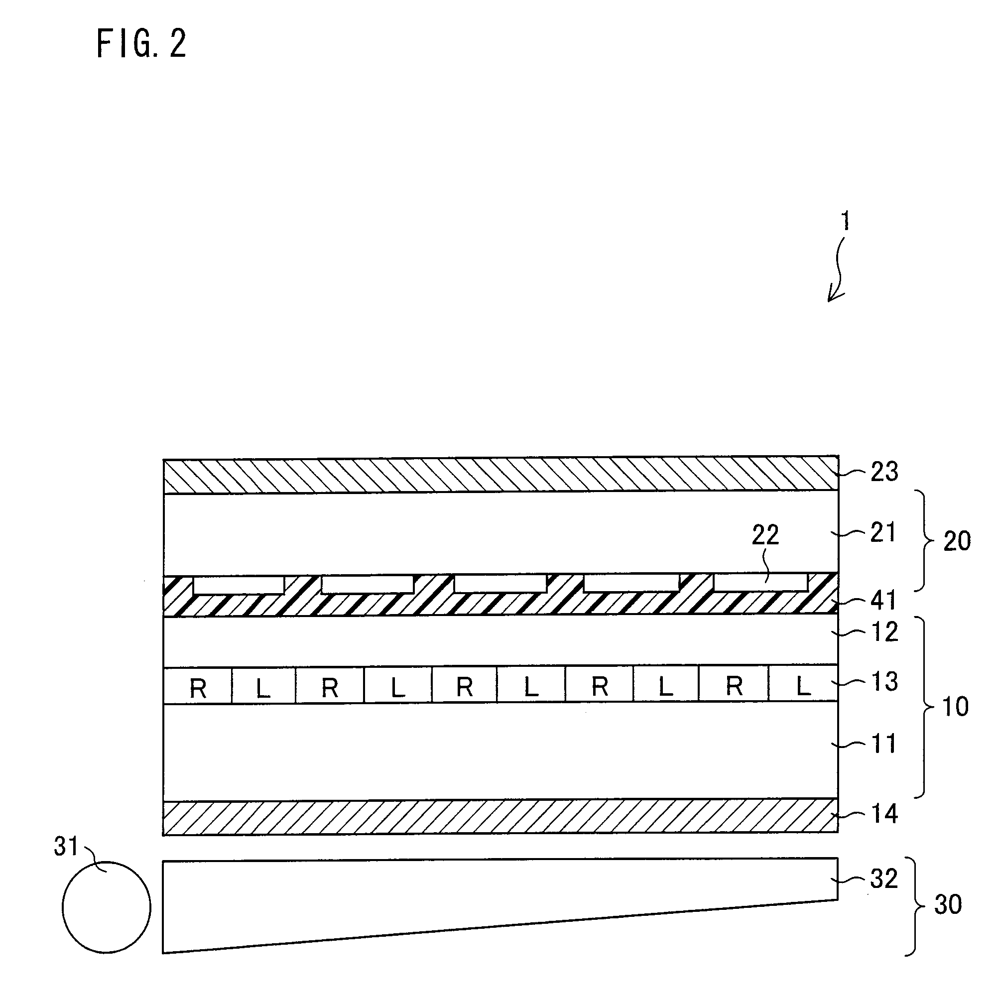
[0038]Firstly, an arrangement of a liquid crystal display device 1 of the present preferred embodiment is schematically illustrated in FIG. 2. As illustrated in FIG. 2, the liquid crystal display device 1 includes, basically, a display panel 10, a parallax barrier 20, and a backlight 30.

[0039]The backlight 30 includes a light source 31 and a reflector 32. By reflecting light, which is radiated from the light source 31, to the display panel 10 by the reflector 32, the backlight 30 irradiates light on the display panel 10. The light source 31 may be an LED (light emitting diode), a CCFT (Cold Cathode Florescent Tube), or CCFL (Cold Cathode Fluorescent Lump), for example.

[0040]The display panel 10 preferably is an active-matrix-type liquid cr...


PUM

PropertyMeasurementUnit
thicknessaaaaaaaaaa
thicknessaaaaaaaaaa
thicknessaaaaaaaaaa

Abstract

A parallax barrier is manufactured by forming a light-blocking layer by patterning a metal layer or a resin layer on a barrier glass in a photolithography step. On a mask used in the photolithography step, some pitches between slits are different, the slits corresponding to portions whereupon the light-blocking layers are to be formed. In addition, on the mask, first pitches (for instance, 100) and second pitches (for instance 99.5), which can be actually formed with accuracy, are formed in a cycle, and the average of such pitches can be accord with a theoretical pitch distance (for instance, 99.99). Thus, in the parallax barrier to be used for a multiple display device, visibility of the entire screen can be improved, and the parallax barrier which can be manufactured by using the mask lithography technology having a limited accuracy, and a method for manufacturing such parallax barrier are provided.

Description

BACKGROUND OF THE INVENTION[0001]1. Field of the Invention[0002]The present invention relates to a parallax barrier for use in combination with a display panel and for permitting each different image to be displayed to different display directions of the display panel. The present invention also relates to a multiple display device including the combination of the display panel and the parallax barrier, the multiple display device being capable of displaying each different image to different display directions. The present invention also relates to a method of manufacturing the parallax barrier.[0003]2. Description of the Related Art[0004]There have been proposed display devices that can display each different image to different directions of one display screen (multiple display). Such multiple display devices are proposed as devices having a display panel in combination with a parallax barrier. Technologies of such multiple display devices are disclosed in documents, such as Japane...

Claims


Application Information

Patent Timeline
Patent Type & Authority Applications(United States)
IPC IPC(8): G02B27/02G02B5/00G03F7/20G02B30/30
CPCG02B27/2214H04N2213/001H04N2013/0463H04N13/0409H04N13/31H04N2013/403G02B30/30G02B30/27
Inventor TANIMOTO, KAZUNORISAITOH, TATSUJI
Owner SHARP KK
Why Eureka
Try Eureka