Microactuator,head gimbal assembly, and magnetic disk drive

a microactuator and head gimbal technology, applied in the direction of magnetic recording, instruments, data recording, etc., can solve the problems of increasing stroke and getting more difficult to improve positioning accuracy, and achieve the effect of suppressing the reduction of the operation quantity of the microactuator and reducing the rigidity

Active Publication Date: 2009-03-26
WESTERN DIGITAL TECH INC
View PDF9 Cites 25 Cited by
  • Summary
  • Abstract
  • Description
  • Claims
  • Application Information

AI Technical Summary

Benefits of technology

[0012]Embodiments of the present invention help to suppress reduction of the operation quantity of a microactuator. According to the embodiment of FIGS. 7(a)-7(c), a microactuator 205 comprises a silicon substrate 251 and a piezoelectric element 255. The silicon substrate 251 has some rigidity and provides elastic counter force to the piezoelectric element 255. In the piezoelectric element 255, a secondary piezoelectric layer 62 is laminated on a primary piezoelectric layer 61 opposite from the silicon substrate 251. The contraction force of the secondary piezoelectric layer 62 acts on the primary piezoelectric layer 61 so that it bends toward the secondary piezoelectric layer 62 opposite from the silicon substrate 251. When the primary piezoelectric layer 61 expands, the contraction force of the secondary piezoelectric layer 62 acts on the primary piezoelectric layer 61 so that it warps against the primary piezoelectric layer 61.

Problems solved by technology

However, it is getting more difficult to improve the positioning accuracy in driving an actuator by a voice coil motor (VCM).
Since the piezoelectric element expands or contracts in response to application of a voltage, increasing the voltage applied to the piezoelectric element results in increasing the stroke.
However, the inventors have found that a microactuator with a piezoelectric element has a problem that elastic deformation of the substrate influences the expansion and contraction stroke of the piezoelectric element (displacement amount in the in-plane direction) to decrease it. FIG. 11 schematically illustrates the expansion and contraction and the deformation of a piezoelectric element 755 bonded onto a substrate 751. FIG. 11 is a conceptual drawing and does not reflect the actual dimensions.

Method used


Image

  • Microactuator,head gimbal assembly, and magnetic disk drive
  • Microactuator,head gimbal assembly, and magnetic disk drive
  • Microactuator,head gimbal assembly, and magnetic disk drive

Examples


Embodiment Construction

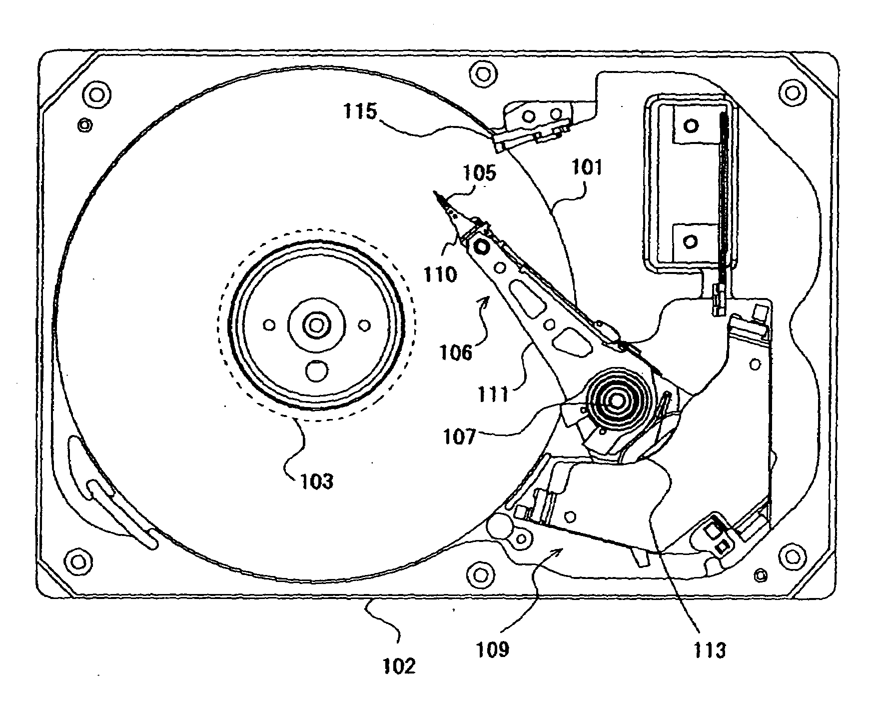
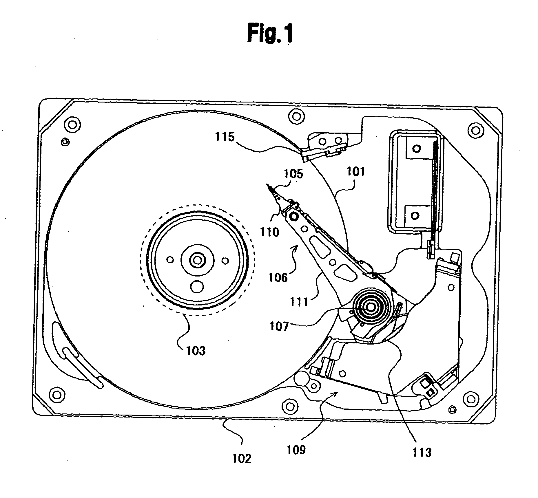
[0024]Embodiments of the present invention relate to a microactuator, a head gimbal assembly, and a magnetic disk device, and more particularly to operation of a microactuator employing a piezoelectric element.

[0025]A microactuator according to an aspect of embodiments of the present invention comprises a platform for fixing a head slider having magnetic recording and reproducing elements thereon, a substrate for holding and rotating the platform, and a piezoelectric element held on the substrate and expanding or contracting in an in-plane direction of the substrate in response to an applied voltage to move the platform in the in-plane direction; the piezoelectric element is located on the substrate and comprises a primary piezoelectric layer for generating an expansion force in the in-plane direction in response to the applied voltage and a secondary piezoelectric layer laminated on the primary piezoelectric layer opposite from the substrate surface for generating a contraction for...


PUM

PropertyMeasurementUnit
voltageaaaaaaaaaa
lengthaaaaaaaaaa
widthaaaaaaaaaa

Abstract

Embodiments of the present invention help to suppress reduction of the operation quantity of a microactuator. According to one embodiment, a microactuator comprises a silicon substrate and a piezoelectric element. The silicon substrate has some rigidity and provides elastic counter force to the piezoelectric element. In the piezoelectric element a secondary piezoelectric layer is laminated on a primary piezoelectric layer opposite from the silicon substrate. The contraction force of the secondary piezoelectric layer acts on the primary piezoelectric layer so that it bends toward the secondary piezoelectric layer opposite from the silicon substrate. When the primary piezoelectric layer expands, the contraction force of the secondary piezoelectric layer acts on the primary piezoelectric layer so that it warps against the primary piezoelectric layer.

Description

CROSS-REFERENCE TO RELATED APPLICATION[0001]The instant nonprovisional patent application claims priority from Japanese Patent Application No. 2007-243149 filed Sep. 19, 2007 and which is incorporated by reference in its entirety herein for all purposesBACKGROUND OF THE INVENTION[0002]Disk drive devices using various kinds of recording disks, such as optical disks, magneto-optical disks, flexible magnetic disks, and the like, have been known in the art. In particular, hard disk drives (HDDs) have been widely used as storage devices of computers and have been one of indispensable storage devices for current computer systems. Moreover, the HDDs have found widespread application to moving image recording / reproducing apparatuses, car navigation systems, cellular phones, and the like, due to their outstanding characteristics.[0003]A magnetic disk used in an HDD has multiple concentric data tracks; each data track records multiple servo data having address information and multiple data se...

Claims


Application Information

Patent Timeline
Patent Type & Authority Applications(United States)
IPC IPC(8): G11B21/24
CPCG11B5/4826G11B5/5552G11B5/4873
Inventor TAKAHASHI, HARUHIDEHIRANO, TOSHIKI
Owner WESTERN DIGITAL TECH INC
Why Eureka
Try Eureka