Material handling vehicle location system

a material handling and location system technology, applied in the direction of vehicle position/course/altitude control, process and machine control, instruments, etc., can solve the problem of inability to grasp the degree of correctness of the position detection in the probability theory, the system structure is not so simple, and the degree of accuracy of the position detection cannot be grasped. the effect of increasing reliability

Active Publication Date: 2009-03-26
NIPPON YUSOKI
View PDF2 Cites 5 Cited by
  • Summary
  • Abstract
  • Description
  • Claims
  • Application Information

AI Technical Summary

Benefits of technology

[0009]The present invention was made in light of problems of the prior art, and the object of the invention is to provide a system for detecting actual position of a material handling vehicle in a warehouse in which a plurality of racks composed of upright frame members and lateral frame members connecting the upright members are installed so that material handling vehicles can travel along the passageway between the racks together with correctness probability of the detected position, so that current position of the material handling vehicle in the warehouse can be detected with increased reliability even if some of the reflections fail to be received by the sensors.

Problems solved by technology

With this location detecting system, a means for allowing a laser beam to scan 360° in a horizontal plane is needed to detecting actual location of a material handling vehicle, and system structure is not so simple.
Further, it correct reading of the reflector plates fails, the controller misjudges the position of the material handling vehicle, and whether the position of the vehicle is detected correctly or not can not be checked, that is, degree of correctness of the detection of the position can not be grasped in point of view of probability theory.
Therefore, with the system, management functions of material handling are still not sufficiently improved.

Method used


Image

  • Material handling vehicle location system
  • Material handling vehicle location system
  • Material handling vehicle location system

Examples


Embodiment Construction

[0035]A preferred embodiment of the present invention will now be detailed with reference to the accompanying drawings. It is intended, however, that unless particularly specified, dimensions, materials, relative positions and so forth of the constituent parts in the embodiments shall be interpreted as illustrative only not as limitative of the scope of the present invention.

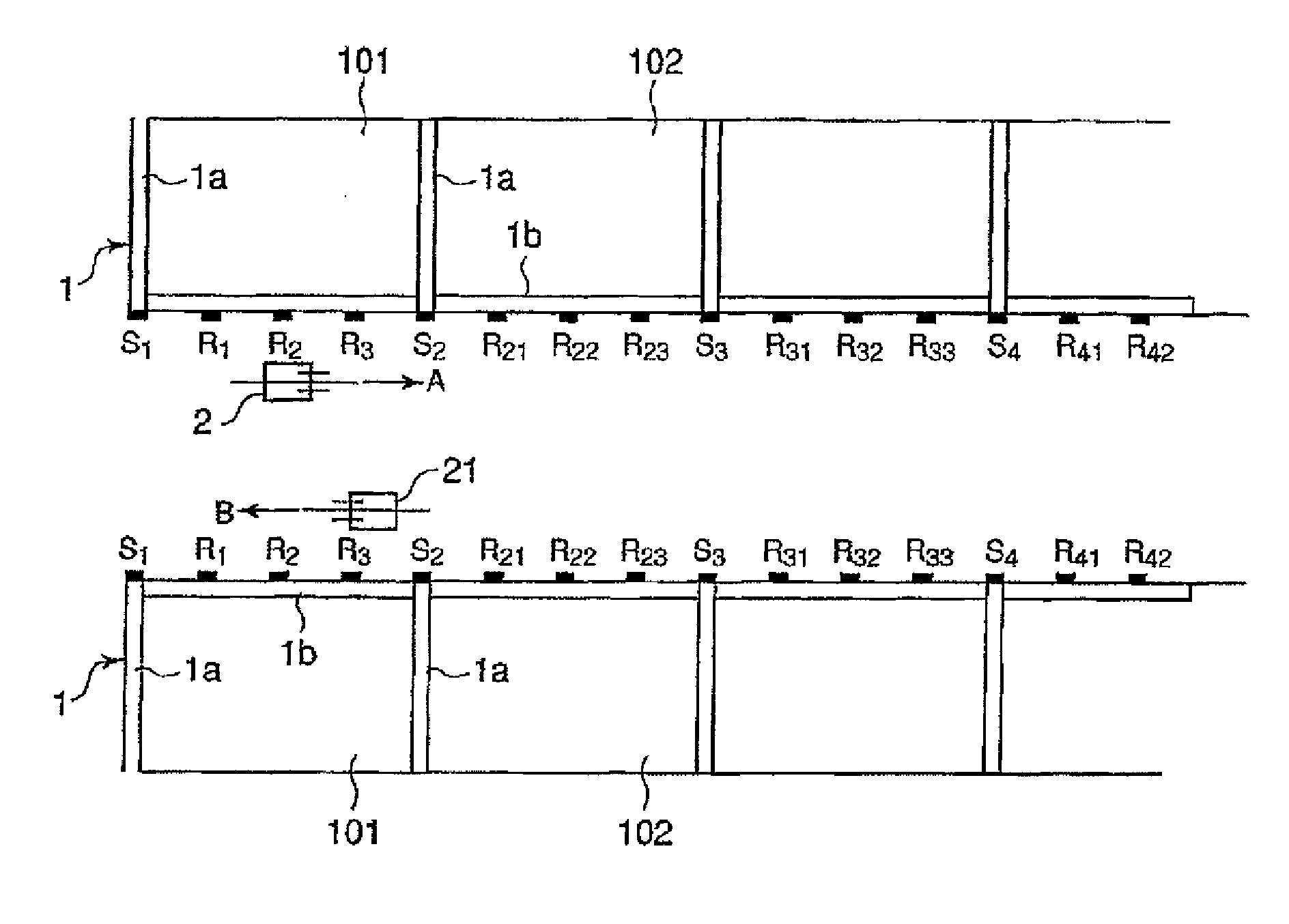
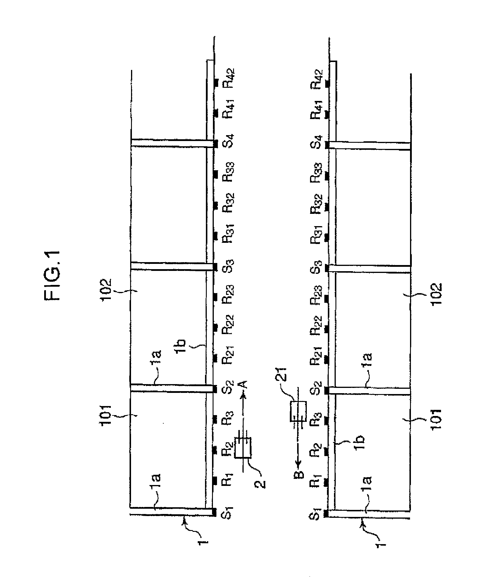
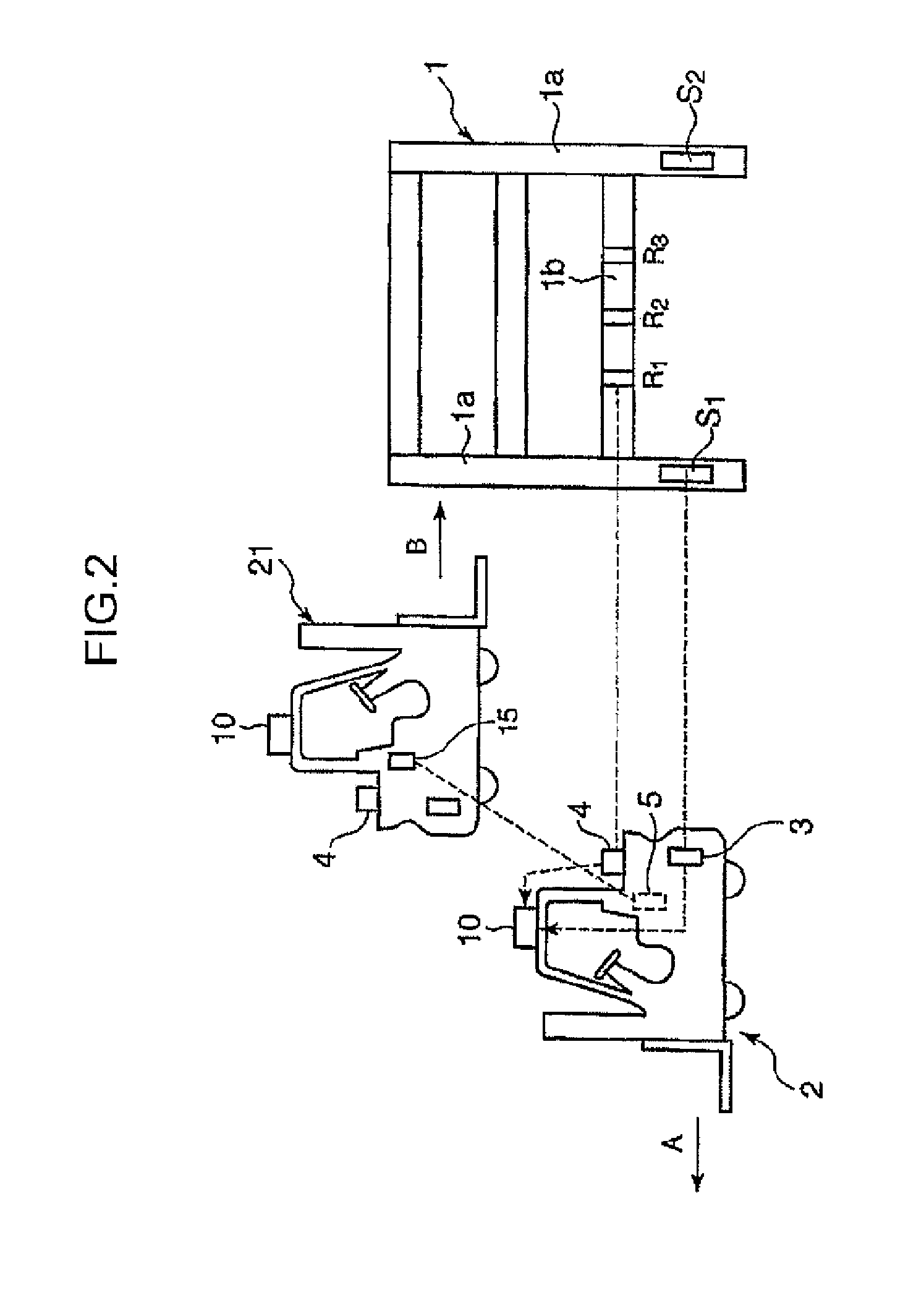
[0036]FIG. 1 is a schematic plan view of a forklift truck location system in a warehouse provided with a plurality of racks to which reflector plates adhered and which are installed so that forklift trucks can travel between them, and FIG. 2 is a schematic side elevation view of one of the racks and forklift trucks traveling in the right and left direction.

[0037]Referring FIGS. 1 and 2, reference numeral 1 is a rack composed of upright frame members 1a and lateral frame members 1b connecting to the upright frame members 1a to form a lattice-shaped rack. Reference numeral 2 and 21 are forklift trucks. The rack 1 ...


PUM


Abstract

The object of the invention is to provide a system which can be constituted quite compactly for detecting actual position of a material handling vehicle in a warehouse in which a plurality of racks composed of upright frame members and lateral frame members connecting the upright members are installed so that material handling vehicles can travel along the passageway between the racks so that current position of the material handling vehicle in the warehouse can be detected with increased reliability even if some of the reflections fail to be received by the sensors.
A first reflector plate S is attached to each of the upright frame members and a plurality of second reflector plates R are attached to the lateral frame member along longitudinal direction thereof, a first sensor 3 and a second sensor 4 each for emitting a light beam and receiving reflection thereof from each of the first and second reflector plates are attached to the vehicle, and a controller is installed on the vehicle to estimate current location of the vehicle based on combination of the number of reflections actually received by the first and second reflector plates and counted by the controller.

Description

BACKGROUND OF THE INVENTION[0001]1. Field of the Invention[0002]The present invention relates to a system for detecting the location where a material handling vehicle currently is in a warehouse in which a plurality of racks composed of upright frame members and lateral frame members connecting the upright members are installed so that material handling vehicles such as forklift trucks can travel between the racks.[0003]2. Description of the Related Art[0004]There has been known systems for detecting the actual location of a material handling vehicle operating material handling in a warehouse, in which the actual position of the vehicle is determined from image data of a photograph taken by a camera attached on the vehicle through pattern matching process or from a light beam or radio waves reflected from reflector plates located at predetermined positions by emitting a light beam or radio waves from a rotating projector attached on the vehicle.[0005]In Japanese Patent No. 3443829 (...

Claims


Application Information

Patent Timeline
Patent Type & Authority Applications(United States)
IPC IPC(8): G08G9/02G06F19/00
CPCB65G1/0421G01B11/002B66F9/0755
Inventor TANAKA, MASAYUKISHINOZAKI, AKIKOOTA, JUNCHOU, TSAI-LIN
Owner NIPPON YUSOKI
Why Eureka
Try Eureka