Exhaust gas purifier and filter regenerator

Inactive Publication Date: 2009-04-02
TOKYO UNIV OF MANNE SCI & TECH
View PDF4 Cites 6 Cited by
  • Summary
  • Abstract
  • Description
  • Claims
  • Application Information

AI Technical Summary

Benefits of technology

[0014]Still further, according to the filter regeneration apparatus of the present invention, the support frame around which the working coil for induction heating is wound is disposed at one end of the casing having the filter unit disposed therein, and the filter unit can be induction-heated an

Problems solved by technology

Such a ceramic material is fragile due to its nature, and is highly likely to be cracked due to, for example, vibration,

Method used


Image

  • Exhaust gas purifier and filter regenerator
  • Exhaust gas purifier and filter regenerator
  • Exhaust gas purifier and filter regenerator

Examples


Embodiment Construction

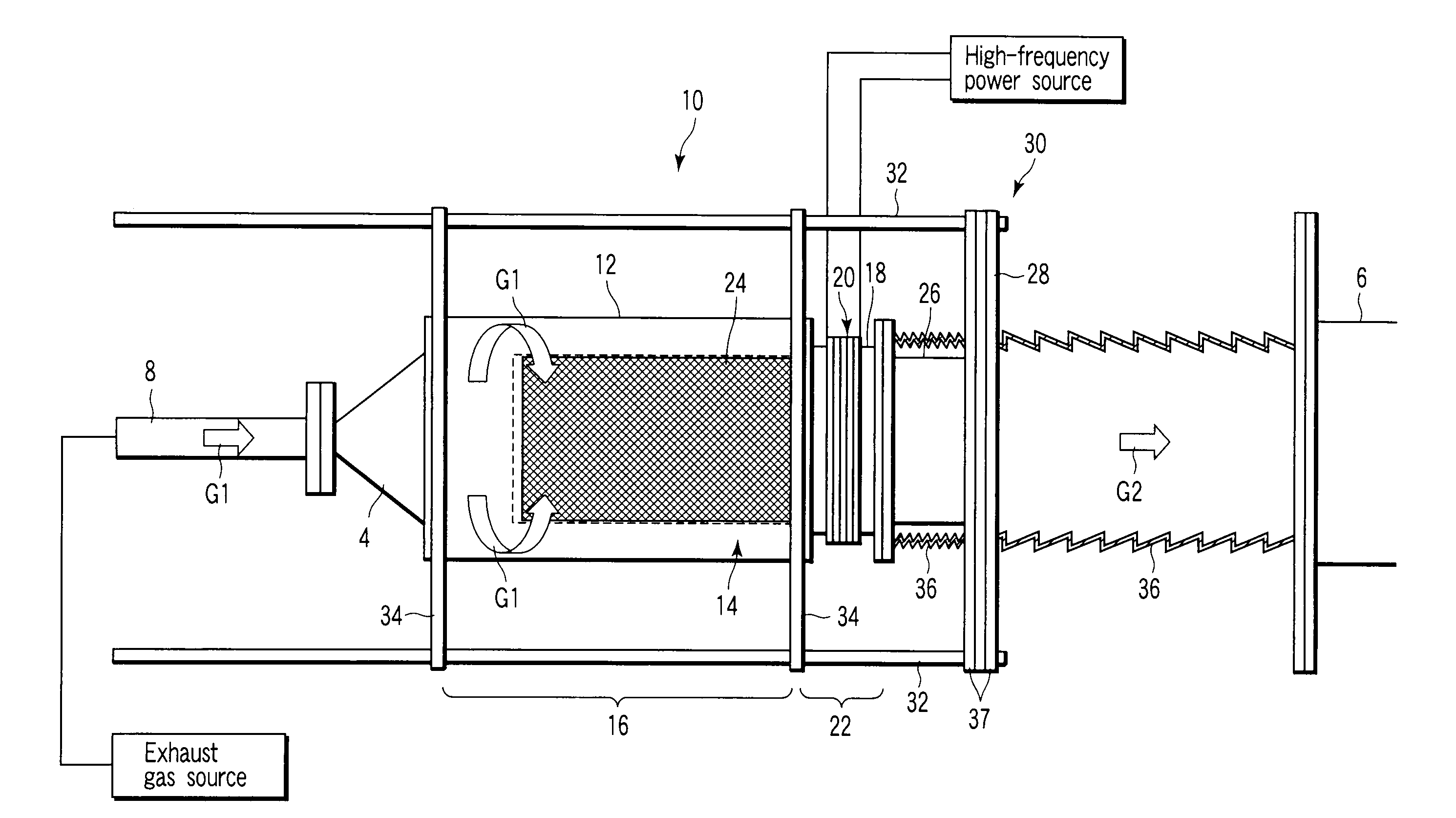
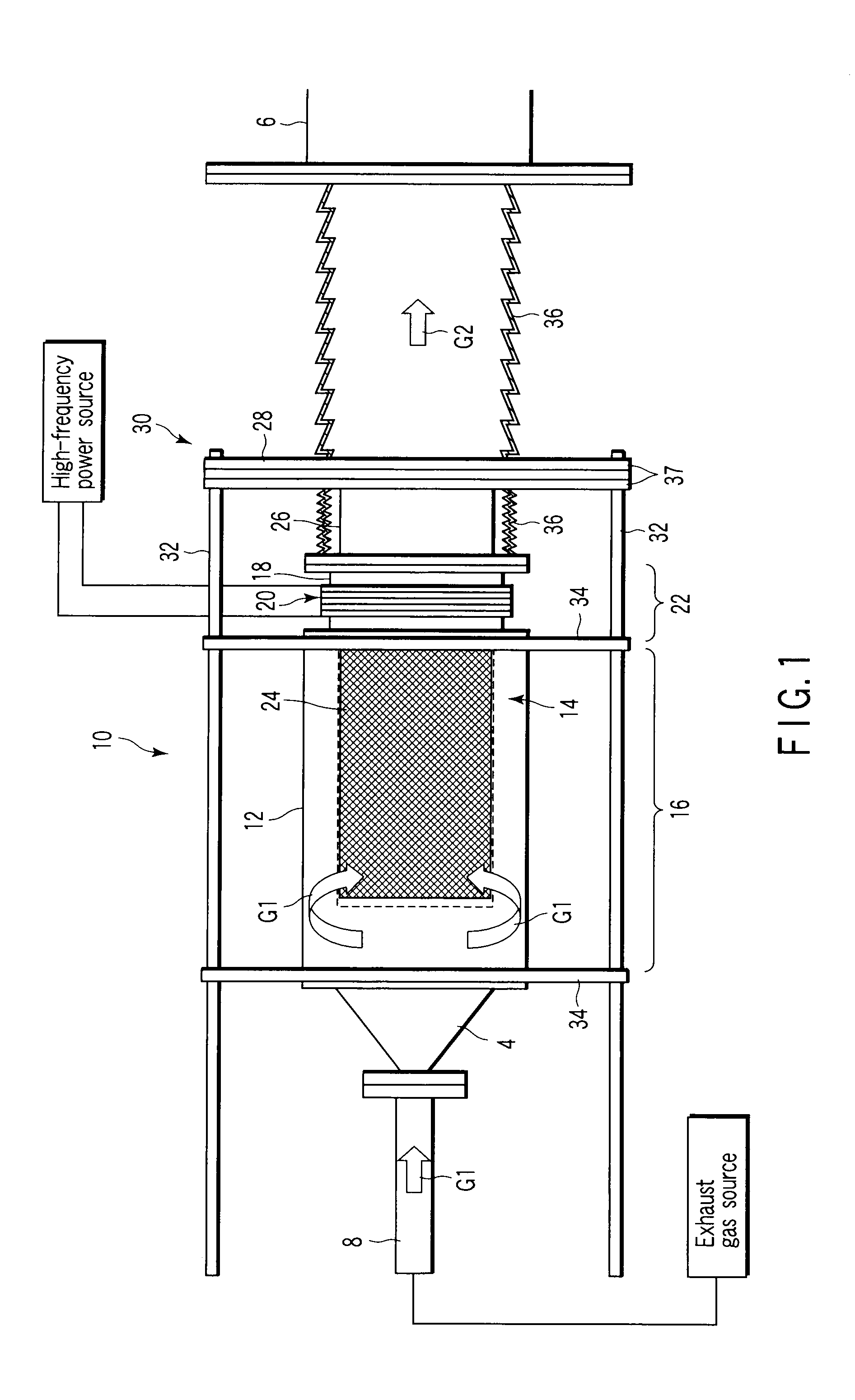
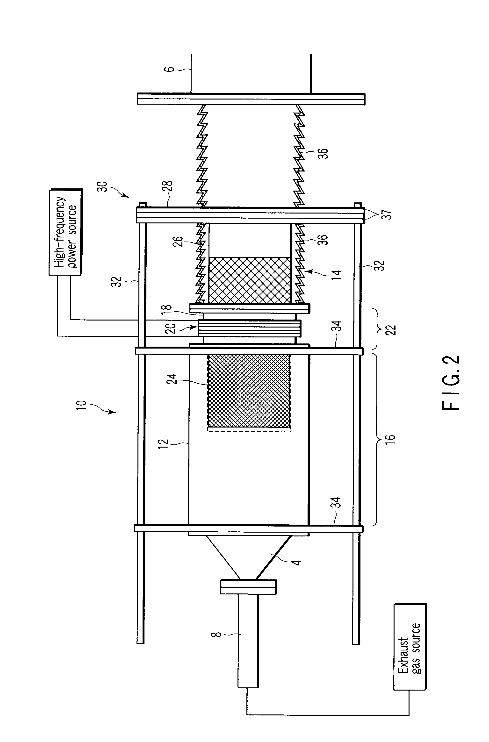
[0018]FIGS. 1 to 3 show an exhaust gas cleaning apparatus 10 according to a preferred embodiment of the present invention. This exhaust gas cleaning apparatus 10 is used to remove particulate matter, that is, particulates from an exhaust gas emitted from an unshown exhaust gas source such as a boiler, waste incinerator or a main or auxiliary diesel engine of, for example, a ship.

[0019]This exhaust gas cleaning apparatus 10 is disposed between a machine-side exhaust duct 8 connected to the outlet of the exhaust gas source via an unshown flexible hose and an outside atmosphere side exhaust duct 6 in communication with the outside air. The exhaust gas cleaning apparatus 10 removes the particulates from an exhaust gas G1 that has flown in, and then discharges a clean exhaust gas G2 to the outside atmosphere side exhaust duct 6.

[0020]This exhaust gas cleaning apparatus 10 is formed of a particulate collecting section 16 where a filter unit 14 to collect particulates in an exhaust gas is ...


PUM

PropertyMeasurementUnit
Lengthaaaaaaaaaa
Flow rateaaaaaaaaaa
Diameteraaaaaaaaaa

Abstract

An exhaust gas cleaning apparatus and a filter regeneration apparatus that are capable of cleaning a large volume of exhaust gas without any increase in size of a nonmagnetic member around which a working coil for induction heating is wound. The exhaust gas cleaning apparatus includes a particulate collecting section and a filter regenerating section placed next to each other in the flow direction of an exhaust gas, and a movable frame. The movable frame holds an extension of a filter unit extending from a casing of the particulate collecting section beyond the support frame of the filter regenerating section, and can move the filter unit in the axial direction of the casing. When the filter unit moved by the movable frame passes through the filter regenerating section, a corresponding part of a holding frame disposed in the filter unit is continuously induction-heated to burn collected particulates, such that the filter unit can be regenerated.

Description

TECHNICAL FIELD[0001]The present invention relates to an exhaust gas cleaning apparatus and a filter regeneration apparatus for removing particulates in an exhaust gas of, for example, a diesel engine, a boiler or an incinerator.BACKGROUND ART[0002]Various forms of diesel particle filters (DPFs) for automobiles have been developed due to the particulate matter emitted from diesel engines causing lung cancer, asthma or allergies. On the other hand, in marine diesel engines, fuel oil of high sulfur content is used, so that it is difficult to apply a technique for the collection, low-temperature burning and removal of particulate matter, that is, particulates, by the combination of an oxidation catalyst and a ceramic filter used for automobiles.[0003]Thus, as described in WO 2004-059135, the inventor of the present application has developed an apparatus for removing fine particles in exhaust gas, wherein a filter unit for collecting particulates in the exhaust gas is stored in a cylind...

Claims


Application Information

Patent Timeline
IPC IPC(8): B01D39/20F01N3/02B01D46/42
CPCB01D39/2086F01N3/027F01N3/023B01D46/0063B01D46/84
Inventor HATANAKA, YOSHIHIRO
Owner TOKYO UNIV OF MANNE SCI & TECH
Why Eureka
Try Eureka