Heat exchanger with divided coolant chamber

Active Publication Date: 2009-04-02
GARRETT TRANSPORATION I INC
View PDF9 Cites 14 Cited by
  • Summary
  • Abstract
  • Description
  • Claims
  • Application Information

AI Technical Summary

Benefits of technology

[0012]Heat exchanger be constructed in this manner, comprising the coolant path dividers or baffles, reduces and/or eliminates the potential for unwanted coolant boiling, and does so in a manner that greatly minimizes unwanted cooling medium pressure drop and the presence of dead zones within the heat exchanger that are otherwise ass

Problems solved by technology

A problem that is known to exist with such shell and tube-type heat exchangers is the unwanted boiling of the coolant within the exchanger during heat exchanger operation.
For example, when such conventional heat exchangers are used to reduce the temperature of an incoming exhaust gas emitted from an internal combustion engine, e.g., when used in conjunction with an exhaust gas recirculation (EGR) system, a high heat flux can create an unwanted boiling of the coolant within the heat exchanger.
Boiling of the coolant is undesired because it

Method used


Image

  • Heat exchanger with divided coolant chamber
  • Heat exchanger with divided coolant chamber
  • Heat exchanger with divided coolant chamber

Examples


Example

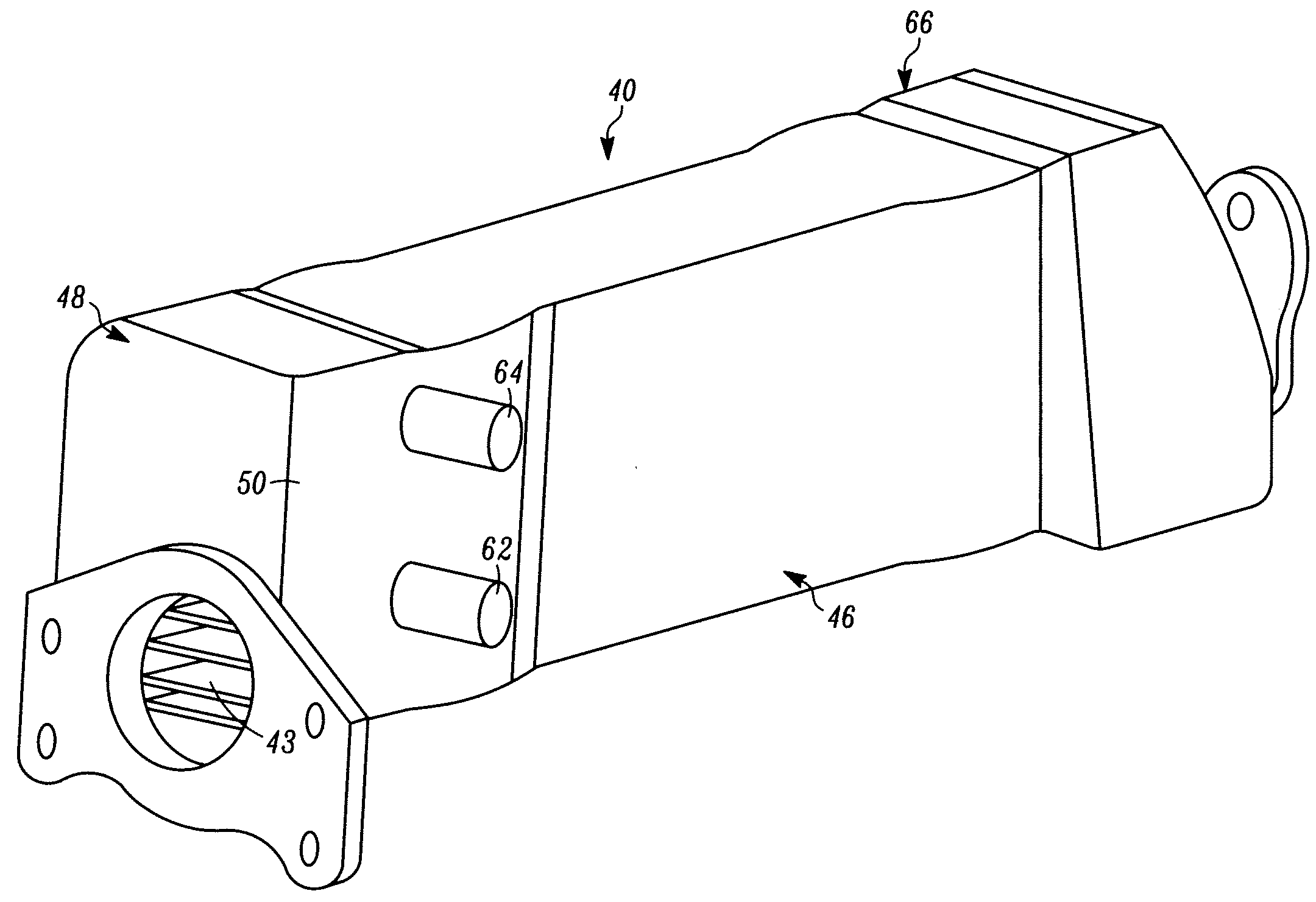
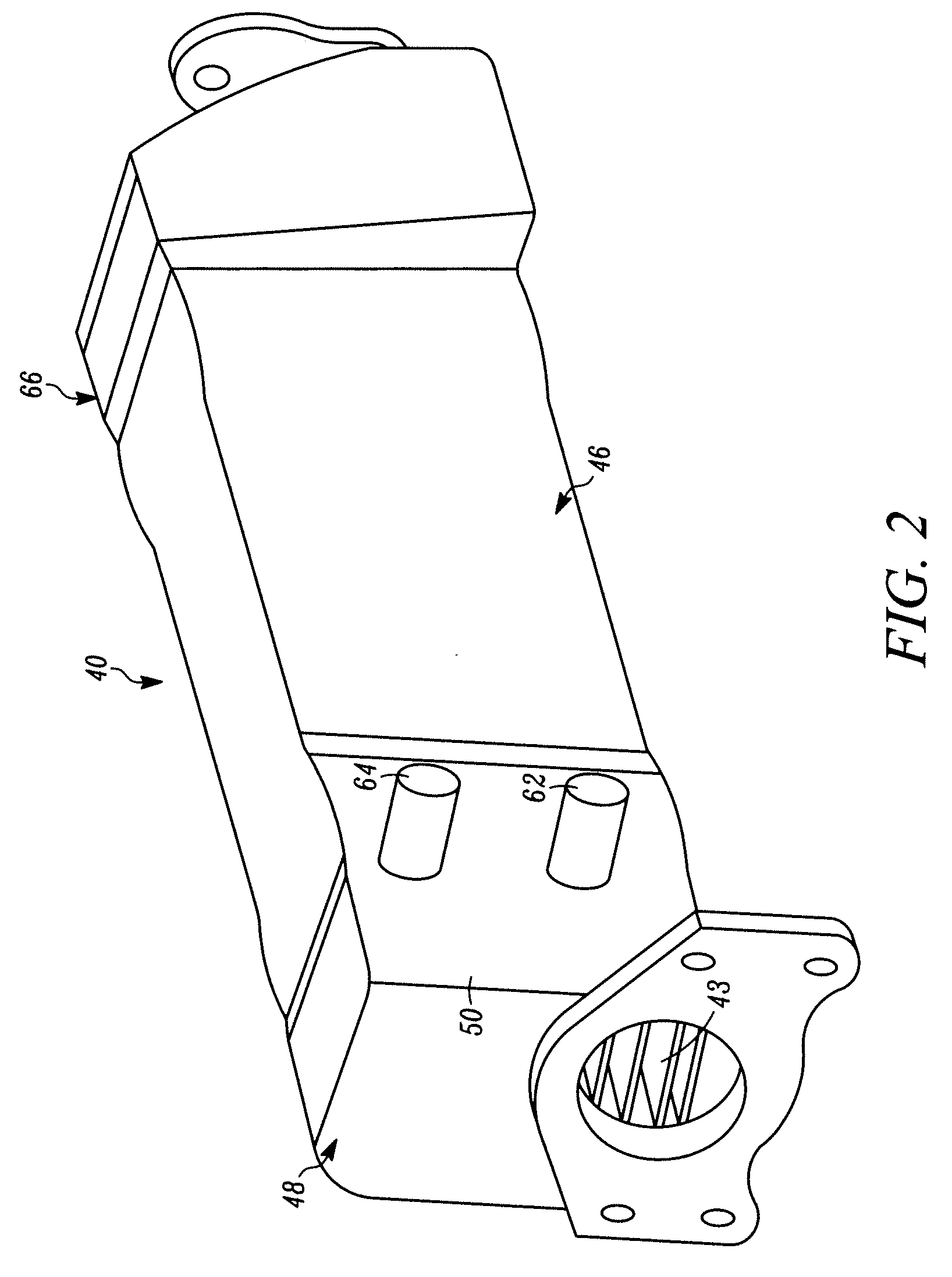
[0018]The present invention relates to heat exchangers used for reducing the temperature of an entering gas or fluid stream. A particular application for the heat exchangers of this invention is with vehicles and, more particularly, is to cool an exhaust gas stream from an internal combustion engine, e.g., as used with an EGR system. However, it will be readily understood by those skilled in the relevant technical field that the heat exchanger configurations of the present invention described herein can be used in a variety of different applications.

[0019]Generally, the invention constructed in accordance with the principles of this invention, comprises a heat exchanger including a stack of elongated, flattened tubes that are enclosed in a surrounding shell. The heat exchanger includes a coolant chamber at each end of the shell, wherein one of the coolant chambers is configured comprising a coolant inlet and coolant outlet, and further comprising one or more dividers or baffles disp...


PUM

PropertyMeasurementUnit
Lengthaaaaaaaaaa
Flow rateaaaaaaaaaa
Distanceaaaaaaaaaa

Abstract

A heat exchanger has a shell and tube stack disposed within a shell inner chamber. A coolant chamber extends from a shell end, accommodates a portion of the tube stack, and has a sidewall that extends outwardly from the tube stack. A divider is disposed within the coolant chamber between the sidewall and tube stack, and extends axially along the chamber to the end of the shell splitting the coolant chamber into inlet and outlet coolant passages. For example, a pair of dividers are disposed within the coolant chamber and are attached to a respective sidewall surfaces. A coolant inlet and outlet is in fluid flow communication with respective inlet and outlet coolant passages. A cooling medium within the heat exchanger flows longitudinally within the inlet coolant passage along the tube stack in a direction opposite from the coolant flow path within the outlet coolant passage.

Description

FIELD OF INVENTION[0001]This invention relates generally to the field of heat exchangers and, more particularly, to shell and tube-type heat exchangers that are specially configured to provide improved coolant flow velocity therein to thereby reduce / eliminate the potential for unwanted coolant boiling within the heat exchanger and thus improve heat exchanger cooling efficiency and extend useful service life.BACKGROUND OF THE INVENTION[0002]The present invention relates to heat exchangers that are generally configured comprising a number of internal fluid or gas passages disposed within a surrounding body. In an example embodiment, the internal passages are designed to accommodate passage of a particular fluid or gas in need of cooling, and the body is configured to accommodate passage of a particular cooling fluid or gas used to reduce the temperature of the fluid or gas in the internal passages by heat transfer through the structure of the internal passages. A specific example of s...

Claims


Application Information

Patent Timeline
IPC IPC(8): F28F3/12B21D53/02
CPCF28D7/1692F28D21/0003Y10T29/4935F28F9/22F28F9/0202
Inventor AGEE, KEITH
Owner GARRETT TRANSPORATION I INC
Why Eureka
Try Eureka