
Electrically powered well servicing rigs

a technology of electric motors and wells, which is applied in the direction of wellbore/well accessories, drilling pipes, hoisting equipment, etc., can solve the problems of apparatuses, and affecting the operation and maintenance of hydraulically-powered motors. , to achieve the effect of reducing or eliminating the leakage of hydraulic fluids

Inactive Publication Date: 2009-04-02
NAT OILWELL VARCO LP
View PDF58 Cites 72 Cited by
  • Summary
  • Abstract
  • Description
  • Claims
  • Application Information

AI Technical Summary

Benefits of technology

[0021]Such systems and methods which significantly reduce or eliminate leakage of hydraulic fluids.

Problems solved by technology

Providing hydraulic power fluid to well servicing rigs and workover rigs has presented a variety of problems.
When hydraulic systems leak, hydraulic fluid is spilled polluting the environment.
Hydraulically-powered motors and apparatuses, especially in multi-motor systems, are relatively heavy; relatively noisy; require a large amount of space on a rig; and are relatively complex and expensive to operate and maintain.
Diesel-powered engine systems for servicing rigs and workover rigs present issues with excessive weight, power efficiency, safety concerns, excessive noise, inefficient manually operated-braking systems, diesel fume pollution and relatively high maintenance costs.

Method used


Image

  • Electrically powered well servicing rigs
  • Electrically powered well servicing rigs
  • Electrically powered well servicing rigs

Examples


Embodiment Construction

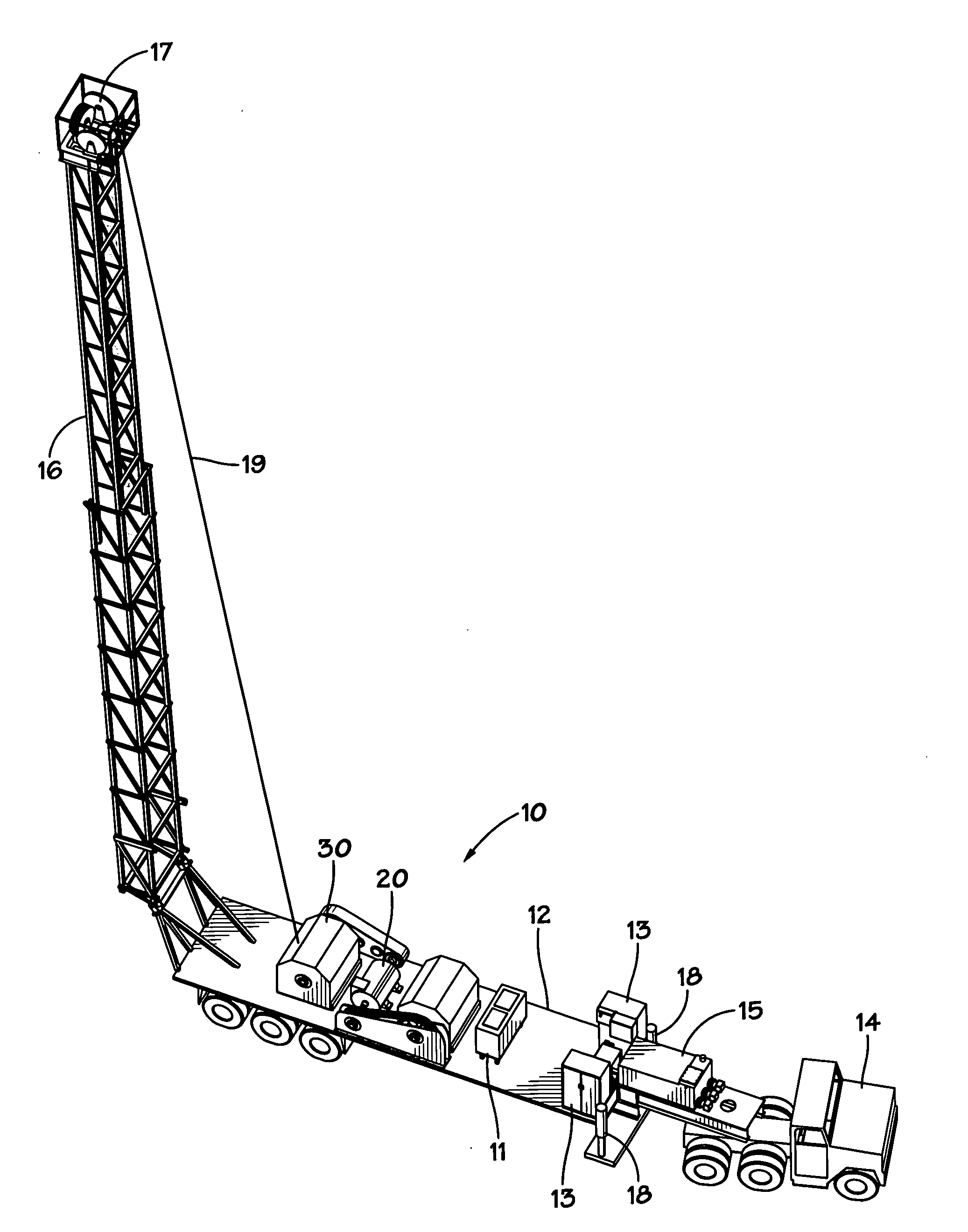
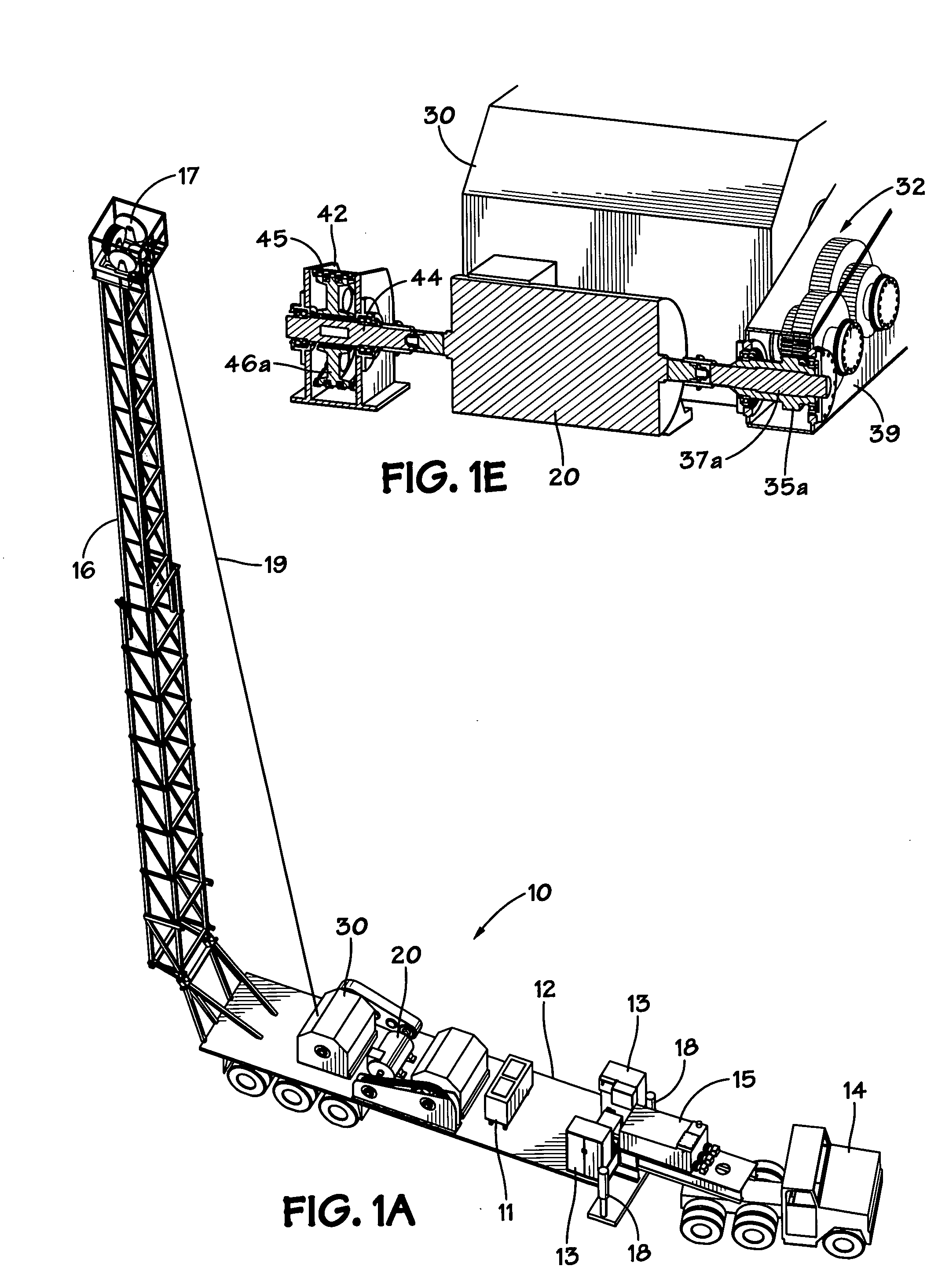
[0047]FIGS. 1A-1G show a system 10 according to the present invention which includes a vehicle with a trailer 12 moved by a truck 14 and a mast 16 which can be raised from the trailer 12 to an erected position as shown in FIG. 1A. Levelling jacks 18 support the trailer 12. Optionally, no separate truck is used and the rig is self-propelled.

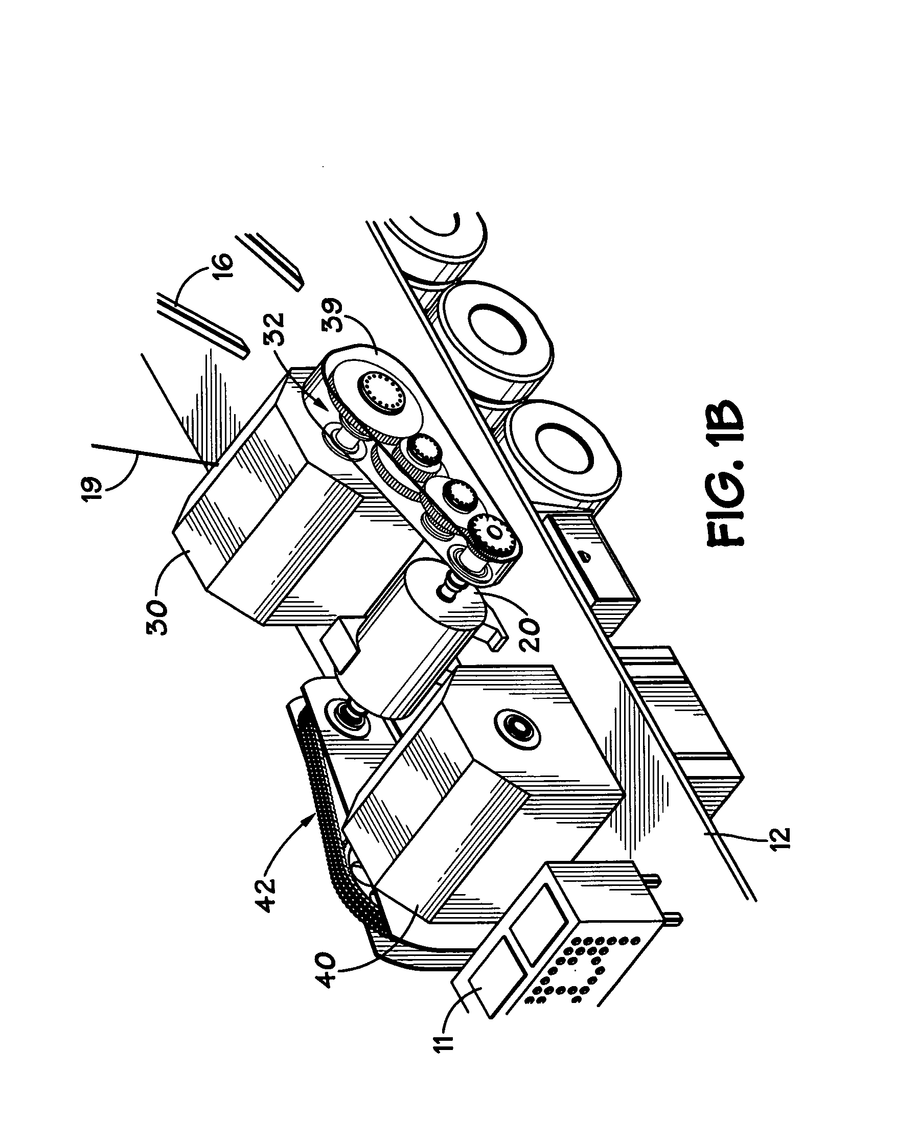
[0048]An electric motor 20 provides power to operate a main winch 30 (also called a drawworks) and a sandline winch 40. The motor 20 has two drive shafts, with one shaft extending from each end of the motor. One drive shaft 21 drives the main drum winch 30 via a gear system 32. Optionally, a chain drive system is used. Another drive shaft 22 drives the sandline winch via a chain drive system 42. A shiftable cutout coupling 23 selectively couples the drive shaft 21 to a shaft 37a of the gear system 32. A housing 39 encloses the gears and shafts.

[0049]A shiftable cutout coupling 24 selectively couples the drive shaft 22 to a shaft 44 of the chain dr...


PUM


Abstract

A mobile land rig for use in wellbore operations. The mobile land rig, in certain aspects, has a vehicle; an erectable mast; winch apparatus (e.g., one or two winches); and electric motor apparatus for powering the winch apparatus. In one aspect there are two winches and one electric motor powers both winches. This abstract is provided to comply with the rules requiring an abstract which will allow a searcher or other reader to quickly ascertain the subject matter of the technical disclosure and is submitted with the understanding that it will not be used to interpret or limit the scope or meaning of the claims, 37 CFR 1.72(b).

Description

BACKGROUND OF THE INVENTION[0001]1. Field of the Invention[0002]The present invention is directed to well servicing rigs; methods of their use; in certain particular aspects to such rigs with electrical motor(s) as power apparatus, e.g., for a winch or winches; and in other particular aspects, to such rigs with a single electric motor to power two rig winches.[0003]2. Description of Related Art[0004]Well servicing rigs, which are not used to drill a wellbore, perform a variety of operations after an oil or gas well has been drilled to get a well ready for production; for example, and not by way of limitation: logging operations; swabbing operations; operations involving the insertion of pipe or tubing into the well; and a perforation operation to perforate tubing.[0005]A typical well servicing system, disclosed in U.S. Pat. No. 6,003,598, has a mobile vehicle / carrier with a collapsible mast or derrick which may be hydraulically raised and lowered by means of hydraulic pistons. A fir...

Claims


Application Information

Patent Timeline
IPC IPC(8): E21B7/02E21B19/22
CPCE21B7/02E21B19/084E21B19/008E21B7/023
Inventor BLOOM, ROBERT LEWIS
Owner NAT OILWELL VARCO LP
Learn More