Dynamic bumps for drag reduction at transonic-supersonic speeds

a technology of transonic-supersonic speed and bumps, applied in the direction of airflow influencers, influencers by shock waves, fuselages, etc., can solve the problems of reducing the lifting capability of the wing, adversely affecting the aerodynamic performance of the aircraft, etc., and achieve the effect of reducing the overall drag

Active Publication Date: 2009-04-02
THE BOEING CO
View PDF31 Cites 21 Cited by
  • Summary
  • Abstract
  • Description
  • Claims
  • Application Information

AI Technical Summary

Benefits of technology

[0006]The present teachings generally include a system for reducing overall drag on an exterior surface of a mobile platform. The system includes a surface on which an airflow forms a boundary layer and a generally normal shockwave. The airflow is at a first velocity that is one of transonic and supersonic. An oscillating jet injects and extracts a jet flow through the surface. The jet flow is at a second velocity that is substantially less than the first velocity. A recirculation region is upstream of the normal shockwave and is disposed at least partially in the boundary layer. The recirculation region is established at least by the oscillating jet. A generally oblique wave is established by the recirculation region and weakens the normal shockwave.

Problems solved by technology

At transonic and supersonic speeds, the strong normal shockwave 16 with its attendant wave drag being the dominant component of drag can adversely impact the aerodynamic performance of the aircraft.
While useful in some implementations, the steady blowing jet can be shown to reduce the lifting capability of the wing because of the relatively high jet momentum and mass flow rate required.

Method used


Image

  • Dynamic bumps for drag reduction at transonic-supersonic speeds
  • Dynamic bumps for drag reduction at transonic-supersonic speeds
  • Dynamic bumps for drag reduction at transonic-supersonic speeds

Examples


Embodiment Construction

[0023]The following description is merely exemplary in nature and is not intended to limit the present teachings, their application or uses. It should be understood that throughout the drawings, corresponding reference numerals indicate like or corresponding parts and features.

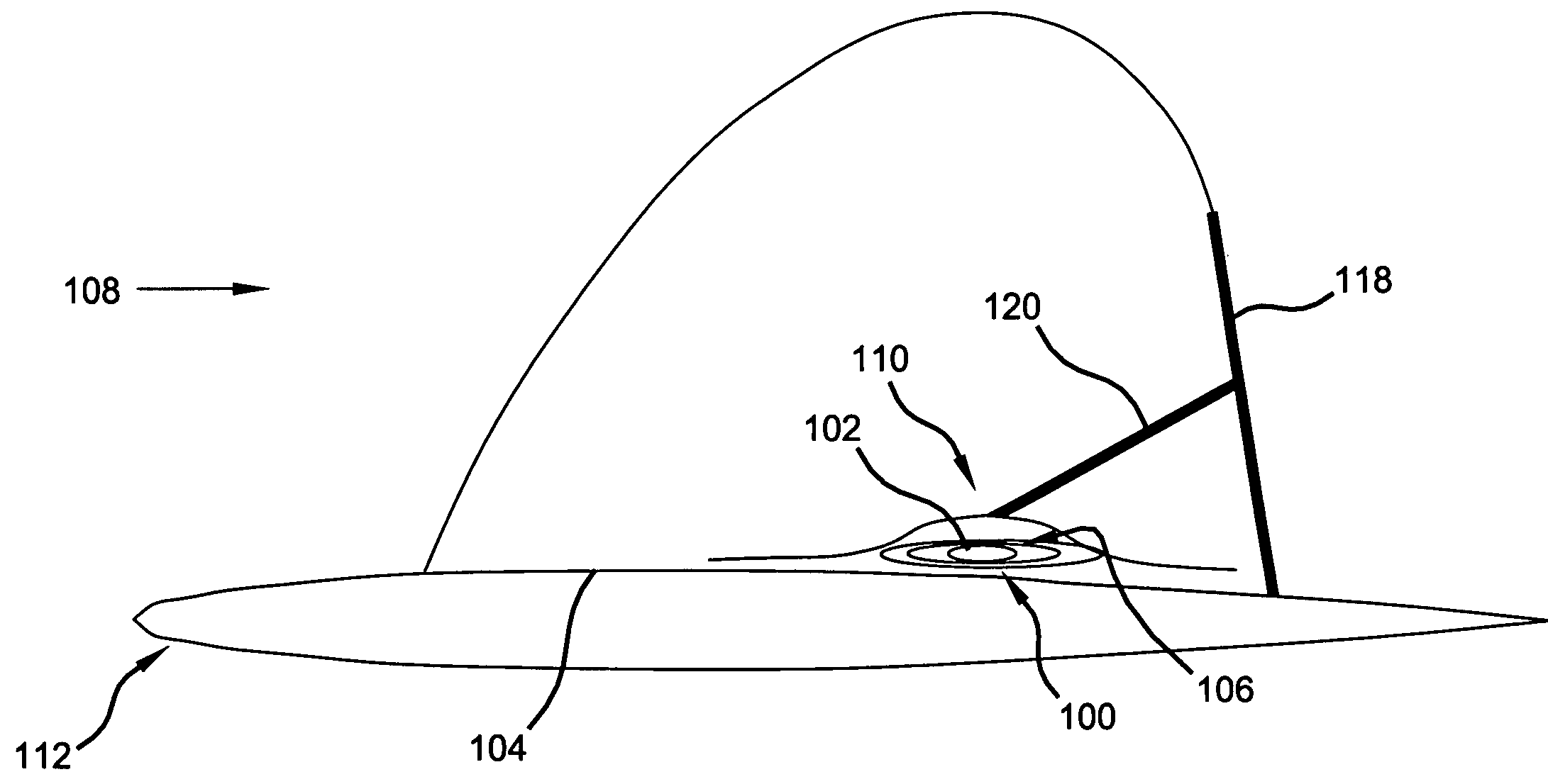
[0024]Various aspects of the present teachings can be applicable to any of a wide range of high speed, airborne mobile platforms, but is particularly useful with jet powered aircraft (e.g., but not limited to, fighter jets, commercial jets, private jets, supersonic dash aircraft, among others). The present teachings are also applicable to both unmanned and manned aircraft, e.g., directly, remotely, via automation, one or more combinations thereof, among others. In addition, various aspects of the present teachings can be applicable to any of a wide range of lift-producing or thrust-producing surfaces for aircraft (e.g., but not limited to, fixed wings, variable geometry wings, rotary wings, right semi-span win...


PUM


Abstract

A system for reducing overall drag of a mobile platform includes a surface on which an airflow forms a boundary layer and a generally normal shockwave. The airflow is at a first velocity that is one of transonic and supersonic. An oscillating jet injects and extracts a jet flow through the surface. The jet flow is at a second velocity that is substantially less than the first velocity. A recirculation region is upstream of the normal shockwave and is disposed at least partially in the boundary layer. The recirculation region is established at least by the oscillating jet. A generally oblique wave is established by the recirculation region and weakens the normal shockwave to reduce the overall drag experienced by the surface.

Description

FIELD[0001]The present teachings relate to adjusting an aerodynamic surface operable in a transonic and a supersonic flow, and more specifically to a recirculation region that is akin to a dynamic bump established by an oscillating jet in the aerodynamic surface that can reduce overall drag.BACKGROUND[0002]The demand for faster and more efficient aircraft is balanced with the cost of producing sufficient thrust to overcome the related drag at the desired speeds. When aircraft operate in a transonic or a supersonic regime, a flow 10 over a surface 12 of a wing 14 can form a strong normal shockwave 16 and a boundary layer 18, as shown in FIG. 1. At transonic and supersonic speeds, the strong normal shockwave 16 with its attendant wave drag being the dominant component of drag can adversely impact the aerodynamic performance of the aircraft. For example, the strong normal shockwave 16 can cause the boundary layer 18 to separate from a portion of the wing 14 and can establish a separati...

Claims


Application Information

Patent Timeline
Patent Type & Authority Applications(United States)
IPC IPC(8): B64C21/08
CPCB64C23/04Y02T50/12B64C2003/148Y02T50/10
Inventor HASSAN, AHMED A.OSBORNE, BRADLEY A.SCHWIMLEY, SCOTTBILLMAN, GARRYBILLMAN, MARY
Owner THE BOEING CO
Why Eureka
Try Eureka