
Multipole coils

a multi-pole coil and coil technology, applied in the direction of coils, magnetic discharge control, printed inductance incorporation, etc., can solve the problems of secondary interference of multi-pole fields and large construction volume, and achieve the effect of improving heat dissipation, precise positioning, and improving heat dissipation

Inactive Publication Date: 2009-04-02
CEOS CORRECTED ELECTRON OPTICAL SYST
View PDF9 Cites 8 Cited by
  • Summary
  • Abstract
  • Description
  • Claims
  • Application Information

AI Technical Summary

Benefits of technology

[0018]Also with regard to the width of the window, the geometric limits which are determined by the number of poles which should be accommodated in the peripheral direction, can be increased in that the multipoles are disposed in different layers to achieve larger windows as the coils overlap. In this case, the geometric limitation on the window width given by the periphery is avoided and can be optimized through experimentation or calculation with regard to the elimination of secondary interfering field effects.
[0051]It is precisely for such configurations in lenses of a particle optical system such as an electron microscope, that the advantages of reduced height in the radial direction are important. The reduced height often permits an otherwise impossible configuration and thereby decreases the size of such a device. Moreover, the reduced constructional height means that the geometry of the lens does not have to be changed or must be only slightly changed. In this fashion, one not only avoids new sources of error, but correctional measures can also be performed in places which were not possible up to this point.

Problems solved by technology

In addition to the generation of torque, force fields, which are suitable for deflecting a beam such as for use in a scanning device, are not lenses.
27), this leads to a very large constructional volume.
The geometry of such multipoles does not lead to the desired production of a pure multipole field, rather causes secondary interfering multipole fields.

Method used


Image

  • Multipole coils
  • Multipole coils
  • Multipole coils

Examples


Embodiment Construction

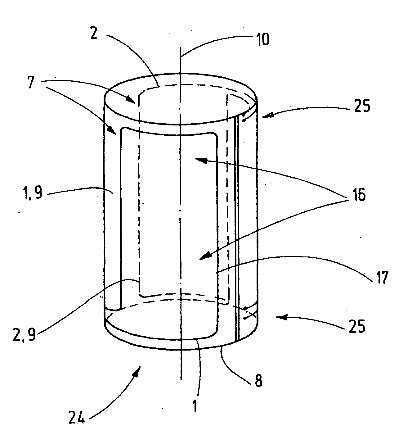
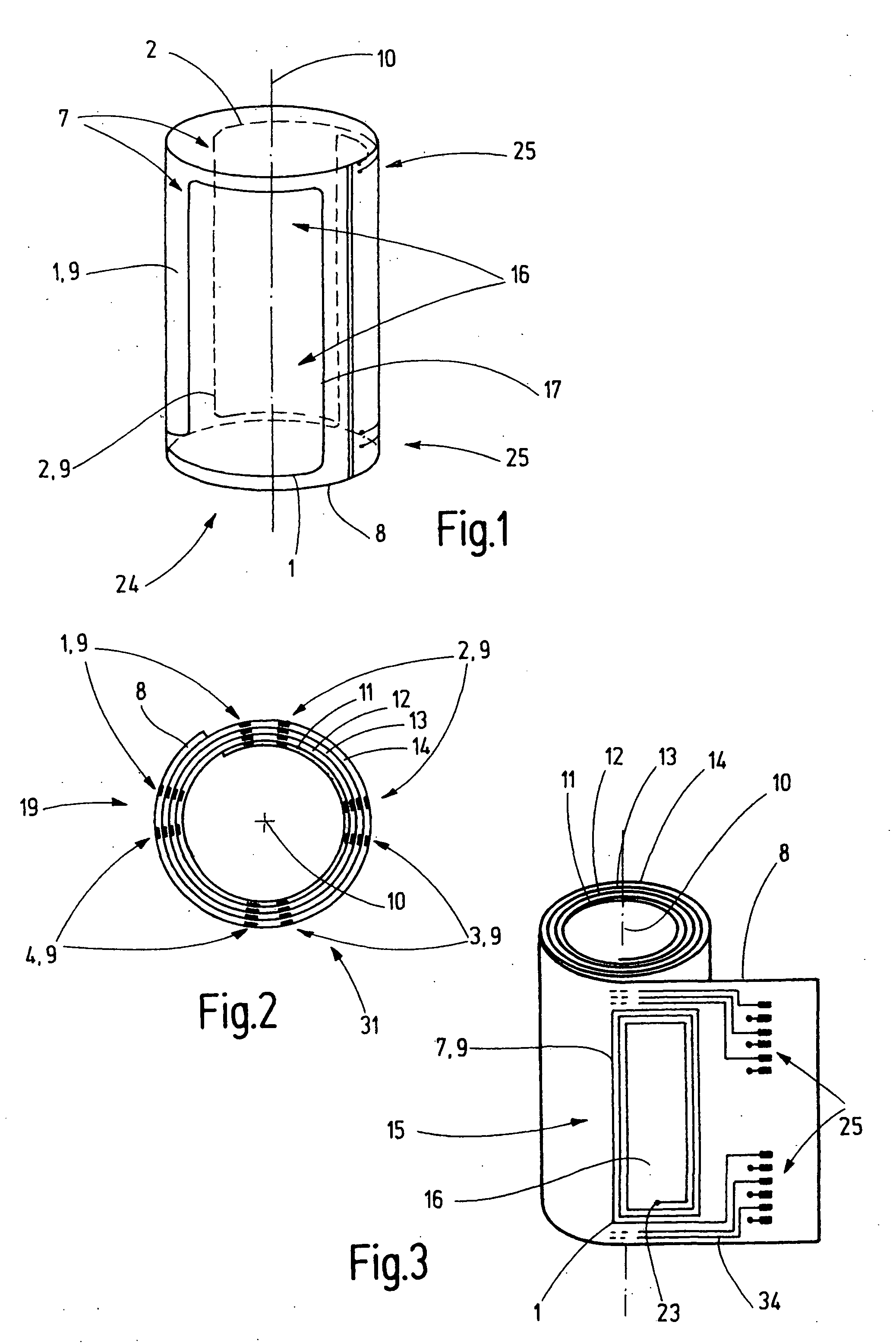
[0064]FIG. 1 shows a simple embodiment of the invention in order to explain the basic principle. Two coils 1 and 2, which each consist of one winding 7, are disposed on a printed circuit board 8 for generating a dipole 24. Each winding 7 is disposed on the printed circuit board 8 in the form of a strip conductor 9, and is loaded with current via connections 25. The windings 7 form rectangular windows 16 with rounded edges, wherein the long sides 17 of the windows 16 are oriented along an imaginary axis 10. The axis 10 is the optical axis when the multipole coils are used in the field of particle optics. The printed circuit board 8 is made from a flexible material and rolled into a cylinder which is hollow inside, such that the two coils 1, 2 concentrically enclose the axis 10.

[0065]FIG. 2 shows a sectional view of one embodiment, in which the printed circuit board 8 is rolled in several printed circuit board layers 11, 12, 13, 14. These multipole coils 1, 2, 3, 4 form a quadrupole 3...


PUM

PropertyMeasurementUnit
angleaaaaaaaaaa
outer diameteraaaaaaaaaa

Abstract

Multipole coils (1, 2, 3, 4, 5, 6) for influencing particle beams have at least two coils (1, 2) which concentrically enclose an imaginary axis (10), wherein a winding (7) made from a flexible circuit board (8) is formed by means of conducting paths (9) disposed thereon for each coil (1, 2, 3, 4, 5, 6) and the circuit boards (8) are rolled into at least one circuit board layer (11, 12, 13, 14). Multipole coils of this kind (1, 2, 3, 4, 5, 6) are utilized for aberration correction in particle optics, wherein the windings (7) of the multipole coils (1, 2, 3, 4, 5, 6) form windows (16) whose width in the peripheral direction is chosen in such a fashion that no secondary interfering fields occur and whose length in the axial direction corresponds at least to its width.

Description

[0001]This application claims Paris Convention priority of DE 10 2007 045 874.8 filed Sep. 25, 2007 the complete disclosure of which is hereby incorporated by reference.BACKGROUND OF THE INVENTION[0002]The invention concerns a multipole coil for influencing a particle beam, having at least two coils which enclose a concentric imaginary axis, wherein each coil has at least one winding made from a flexible circuit board and constructed by means of conducting paths disposed thereon, wherein the circuit board is rolled into at least one circuit board layer.[0003]U.S. Pat. No. 3,702,450 discloses a multipole element of the above-mentioned kind. Towards this end, two coils, each having two halves, are disposed on either side of a beam and rotated through 90 degrees to deflect the beam in the x and y directions. This is especially useful for a scanning beam used to produce an image on a display. An example thereof is a television vacuum tube screen. The coils have substantially spiral shap...

Claims


Application Information

Patent Timeline
Patent Type & Authority Applications(United States)
IPC IPC(8): H01J3/14
CPCH01F5/003H01J29/762H01J29/768H01J37/153Y10T29/4902H01J2237/141H05K1/0393H05K1/165H01J37/26H01J1/50
Inventor ZACH, JOACHIMKALLENBACH, MATTHIAS
Owner CEOS CORRECTED ELECTRON OPTICAL SYST
Learn More