Hall-effect based linear motor controller

a controller and linear technology, applied in the field of linear motion control, can solve the problems of long response time to changes in the position of the motor, difficult to achieve precise linear motion control, and difficult to close the loop

Active Publication Date: 2009-04-02
ALLEGRO MICROSYSTEMS INC
View PDF41 Cites 63 Cited by
  • Summary
  • Abstract
  • Description
  • Claims
  • Application Information

AI Technical Summary

Benefits of technology

[0010]Particular implementations of the invention may provide one or more of the following advantages. The internal sensor-to-driver feedback can compensate for linear motion device (e.g., voice coil actuator, linear motor, speakers) non-linearities as well as mechanical hysteresis. In camera lens focusing applications, the determination of the lens displacement range in conjunction with the sensor-to-driver feedback can calibrate the control to a specific lens assembly.

Problems solved by technology

Closed-loop control of this kind is not without problems, however.
Such operation results in long response times to changes in the motor's position.
Also, precise linear motion control may be difficult to achieve due to hysteresis in the motor's mechanical movement.

Method used


Image

  • Hall-effect based linear motor controller
  • Hall-effect based linear motor controller
  • Hall-effect based linear motor controller

Examples


Embodiment Construction

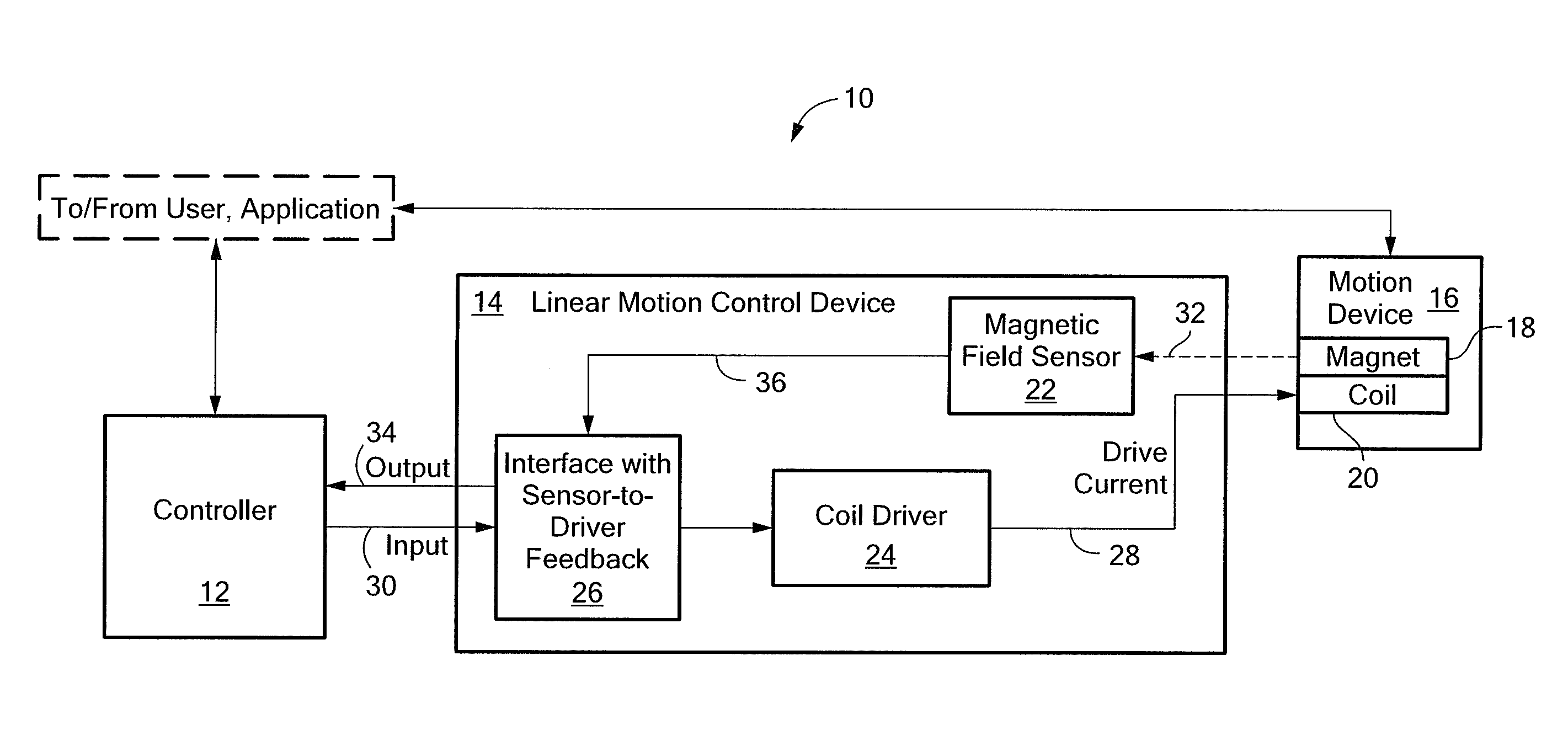
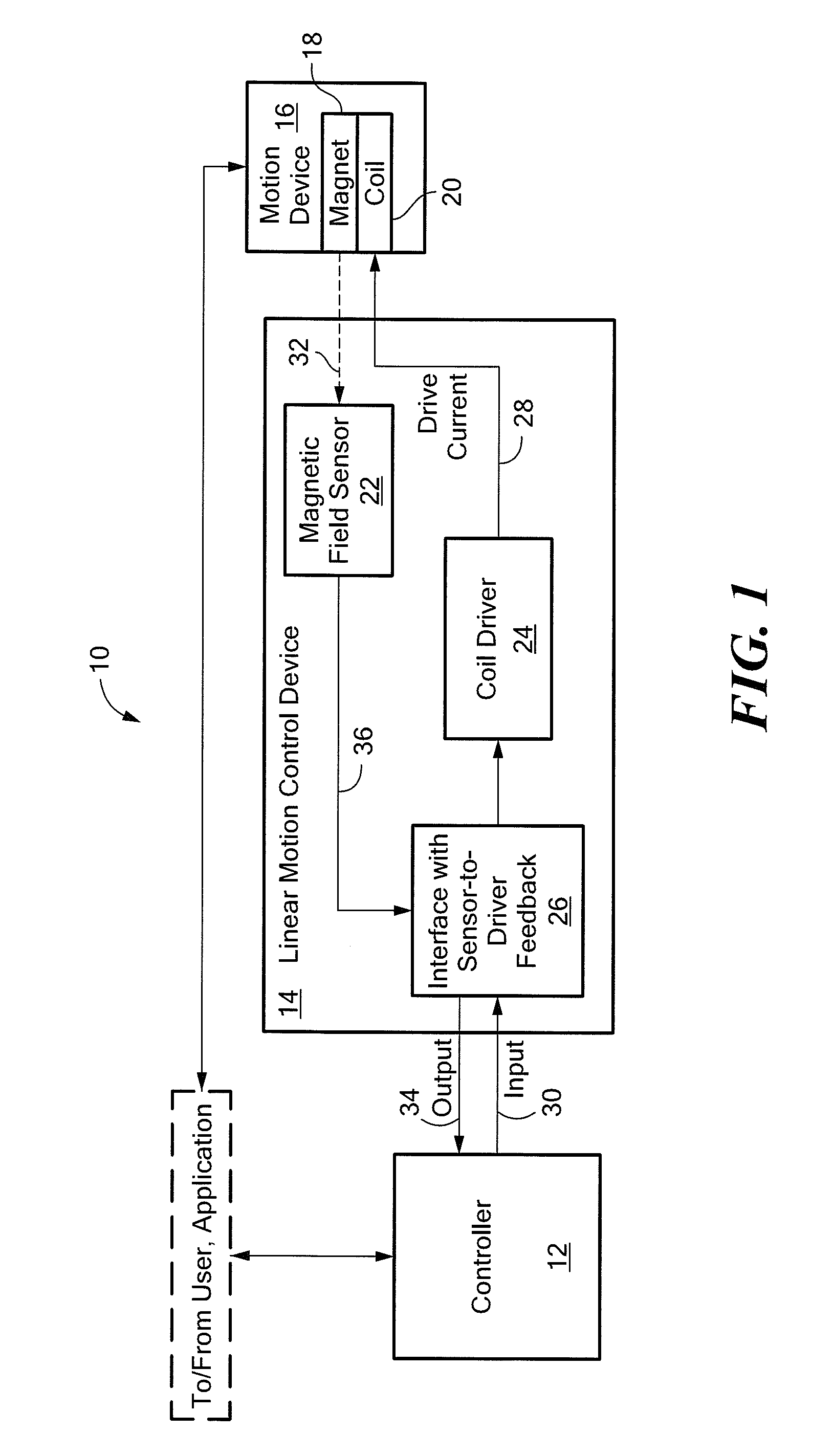
[0022]FIG. 1 shows a control system 10 that provides closed-loop linear motion control to a positioning application. The control system 10 includes a controller 12 connected to a linear motion control device (or “device”) 14. The control system 10 also includes a motion device 16, which includes a magnet 18 and a coil 20. In the described embodiments, the magnet 18 is movable relative to the coil 20. The control system 10 controls the movement of the magnet 18 with the coil 20. The motion device 16 may be any type of linear motion device, for example, a linear motor or linear voice coil actuator. The positioning application may be any application that involves or utilizes linear displacement of such a motion device's magnet.

[0023]The linear motion control device 14 includes a magnetic field sensor 22, a coil driver 24 and an interface 26. The magnetic field sensor 22 may be any magnetic field sensing device, for example, a Hall-effect sensor (Hall sensor) or some kind of magneto-res...


PUM


Abstract

A linear motion control device for use in a linear control system is presented. The linear motion control device includes a coil driver to drive a coil that, when driven, effects a linear movement by a motion device having a magnet. The linear motion control device also includes a magnetic field sensor to detect a magnetic field associated with the linear movement and an interface to connect an output of the magnetic field sensor and an input of the coil driver to an external controller. The interface includes a feedback loop to relate the magnetic field sensor output signal to the coil driver input.

Description

CROSS-REFERENCE TO RELATED APPLICATIONS[0001]Not applicable.STATEMENT REGARDING FEDERALLY SPONSORED RESEARCH[0002]Not applicable.FIELD OF THE INVENTION[0003]This invention relates generally to linear motion control.BACKGROUND OF THE INVENTION[0004]Closed-loop control in a linear motion control system does not require adjustments to be made in order to achieve a desired output (or maintain a constant output) despite varying conditions. Typically, closed-loop control is performed by a microcontroller executing firmware that compares the system's output signal with a desired command to determine the drive for the system. Thus, drive input is adjusted until the output signal matches the desired command.[0005]In some linear positioning applications, the microcontroller uses output signal data from a number of different components, including a position sensor. For example, in small linear motor applications, a magnetic field sensor such as a Hall-Effect sensor may be used to sense motor p...

Claims


Application Information

Patent Timeline
Patent Type & Authority Applications(United States)
IPC IPC(8): G01B7/04G02B7/09G03B13/36
CPCG01D5/145G02B7/102G03B13/36H02K11/0021H04N5/23212H02P6/006H02P25/028H02P25/06H04N5/2253H02K41/0352H02K11/215H02P25/034H04N23/54H04N23/673H02P25/066
Inventor DAVID, PAULMILANO, SHAUN D.
Owner ALLEGRO MICROSYSTEMS INC
Why Eureka
Try Eureka