Inkjet printer

Inactive Publication Date: 2009-04-02
OCE TECH
View PDF4 Cites 2 Cited by
  • Summary
  • Abstract
  • Description
  • Claims
  • Application Information

AI Technical Summary

Benefits of technology

[0009]An object of the present invention is to obviate the above problems and to enlarge the variety of possible signal courses in time when using two signal generators for each piezo element. Each signal generator of the two signal generators applies a signal to another electrode of the piezo element. In this way, a desired voltage reach for a signal is half of the voltage over the piezo element, resulting in the use of less costly signal generators.

Problems solved by technology

It is generally known from integrated circuit (IC) technology that integrated circuits become more expensive when the voltage reach of such a circuit becomes larger.
This is particularly disadvantageous, since the cost growth is not linear with the reach growth, but takes discrete steps of technical adaptations superior to linear growth.
The use of just one signal generator implemented as an integrated circuit is therefore expensive, since the voltage reach has to be relatively large.
A disadvantage of this device is that you need two kinds of voltage sources, a positive and a negative voltage source.
This increases the complexity of the structure, thereby undesirably increasing the overall cost.
Disadvantageous of this arrangement is that for each signal generator being out of order, a plurality of piezo elements is not useable any more, for example a complete row of piezo elements or a complete column of piezo elements.

Method used


Image

  • Inkjet printer
  • Inkjet printer
  • Inkjet printer

Examples


Embodiment Construction

[0035]The present invention will now be described with reference to the accompanying drawings, wherein the same reference numerals have been used to identify the same or similar elements throughout the several views.

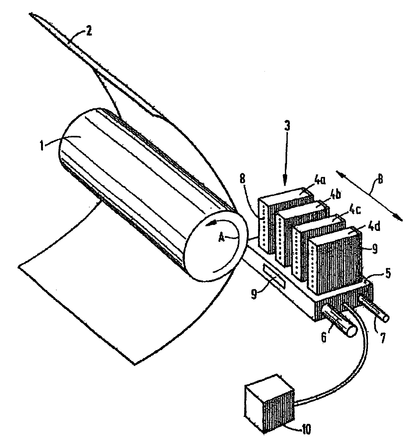
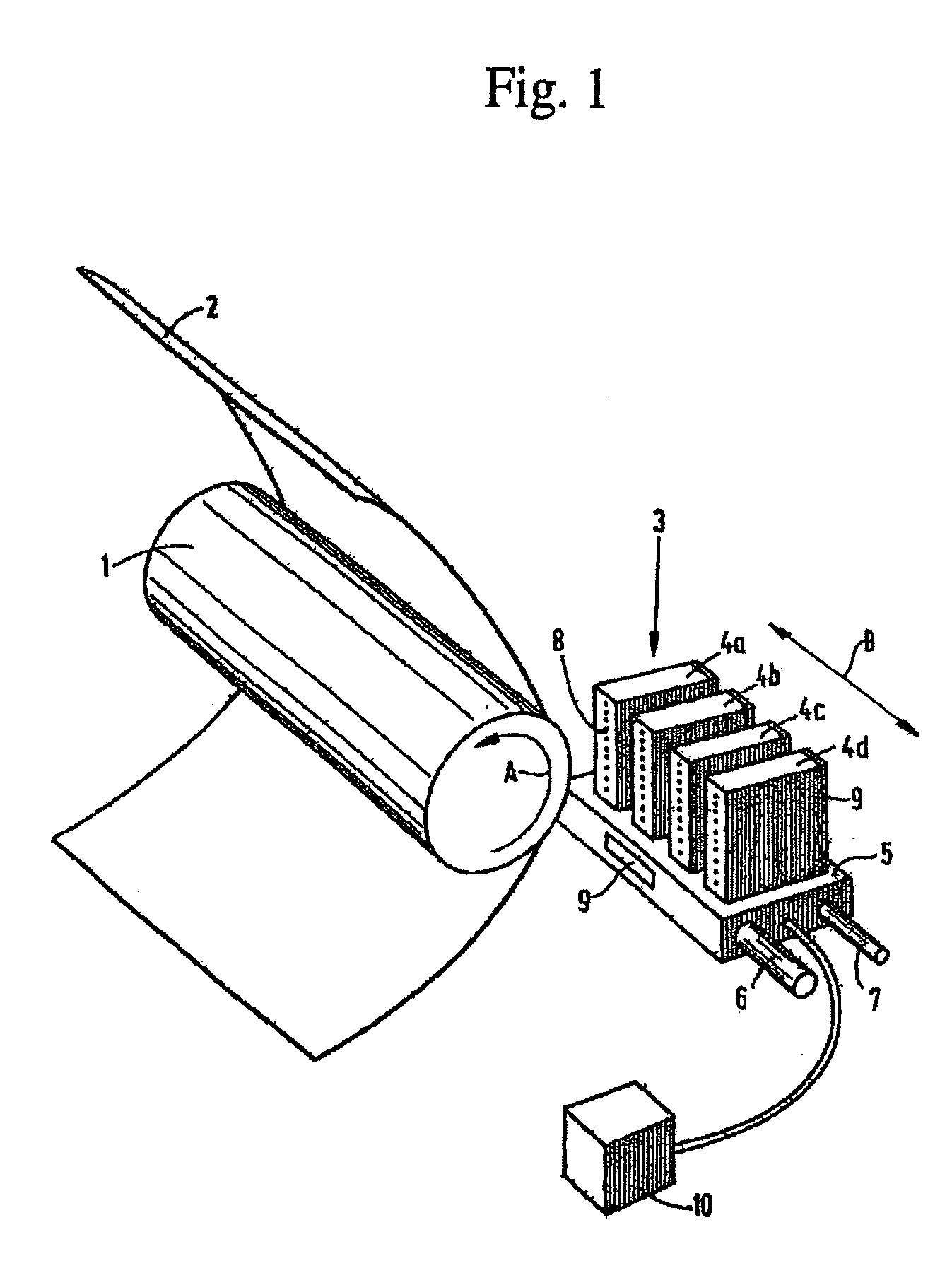
[0036]An inkjet printer is shown in FIG. 1. According to this embodiment, the printer comprises a roller 1 used to support a receiving medium 2, such as a sheet of paper or a transparency, and to move it along the carriage 3. The carriage 3 comprises a carrier 5 on which four print heads 4a, 4b, 4c and 4d have been mounted. Each print head contains its own color, in this case cyan (C), magenta (M), yellow (Y) and black (K) respectively. The print heads are heated using heating elements 9, which have been fitted to the rear of each print head 4 and to the carrier 5. The temperature of the print heads is maintained at the correct level by application of central control unit 10 (controller).

[0037]The roller 1 may rotate around its own axis as indicated by arrow A. In this m...


PUM


Abstract

An inkjet printer includes a substantially closed ink duct in which ink is situated. The duct is operationally connected to a piezo-element,. The piezo-element is actuated with a number of actuation signals with appropriate waveforms, generated by a first and second signal generator in order to eject ink drops from the duct nozzle. A pressure wave is generated in the duct by an actuation pulse. The pressure wave causes a deformation of a piezo-element, which generates an electric signal as a result. The waveforms of the first and second signal may be different and do not have to be directly subsequent in time.

Description

CROSS-REFERENCE TO RELATED APPLICATIONS[0001]This application claims priority under 35 U.S.C. §119(a) to Application No. 07117332.2, filed in Europe on Sep. 27, 2007, the entirety of which is expressly incorporated herein by reference.BACKGROUND OF THE INVENTION[0002]1. Field of the Invention[0003]The present invention relates to an inkjet printing apparatus, including a print head with a plurality of ink ducts and a plurality of piezo elements. Each of the plurality of piezo elements is operationally coupled to one of the plurality of ink ducts and includes a first electrode and a second electrode.[0004]2. Description of Background Art[0005]Inkjet printers having piezo elements are well known in the background art. In these inkjet printers, each ink duct (also referred to as ink chamber) is operationally connected to a piezo element. By actuating a piezo element, so that it deforms, a volume change is achieved in the ink duct associated with this piezo element. The resulting pressu...

Claims


Application Information

Patent Timeline
IPC IPC(8): B41J2/045
CPCB41J2/04541B41J2/04581B41J2002/14354B41J2/04596B41J2/04588
Inventor SIMONS, JOHANNES M.SCHRIJVER, ERWIN
Owner OCE TECH
Why Eureka
Try Eureka