Ink-jet recording device

a recording device and irradiation intensity technology, applied in the field of irradiation recording devices, can solve the problems of high irradiation intensity, increased device cost, low image quality, etc., and achieve the effect of reducing the intensity of light traveling, reducing maintenance frequency, and high intensity

Inactive Publication Date: 2009-04-02
FUJIFILM CORP
View PDF10 Cites 22 Cited by
  • Summary
  • Abstract
  • Description
  • Claims
  • Application Information

AI Technical Summary

Benefits of technology

[0025]According to the invention, by providing the fluorescent lamp with a reflective film and a phosphor film each having an aperture formed therein and by forming the apertures so as to have such shapes that the aperture angles satisfy the above-defined ranges or setting the transmittance of the reflective film to not more than 10%, the recording medium side can be irradiated with high intensity light while reducing the intensity of light traveling in other directions even in the case where the fluorescent lamp used is inexpensive.
[0026]An image can be thus cured to a desired state even in the case where the recording medium travels at a high speed. Light is prevented from reaching the ink-jet head to cause nozzle clogging or this phenomenon is suppressed to enable the maintenance frequency to be reduced.
[0027]As a result, prints having high-resolution and high-quality images formed therein can be rapidly produced for a long time in a consistent manner. Use of the fluorescent lamp enables the light irradiation unit and hence the device to be manufactured at a low cost. Provision of the reflective film within the bulb of the fluorescent lamp enables the light irradiation unit and hence the image curing means to be downsized because it is not necessary to provide space for disposing a reflective member such as a reflector on the circumference of the fluorescent lamp.

Problems solved by technology

However, even if the light irradiating means are disposed downstream of the heads for the respective colors, deposition interference that adjacent dots are merged together on a recording medium or on ink cured after ejection from an ink-jet head disposed further upstream in the direction of travel of the recording medium, may occur to lower the image quality.
However, light irradiating means having a high irradiation intensity is expensive and therefore involves an increased device cost.

Method used


Image

  • Ink-jet recording device
  • Ink-jet recording device
  • Ink-jet recording device

Examples


Embodiment Construction

[0042]The ink-jet recording device according to the present invention is described more fully below based on the embodiments shown in the accompanying diagrams.

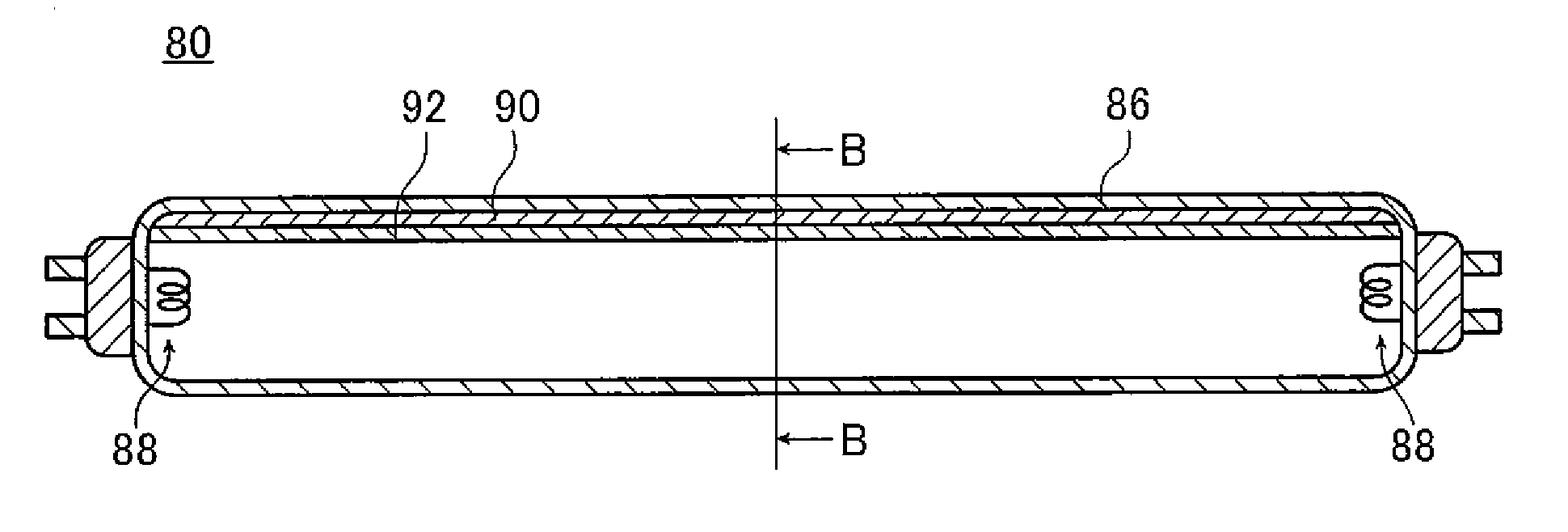
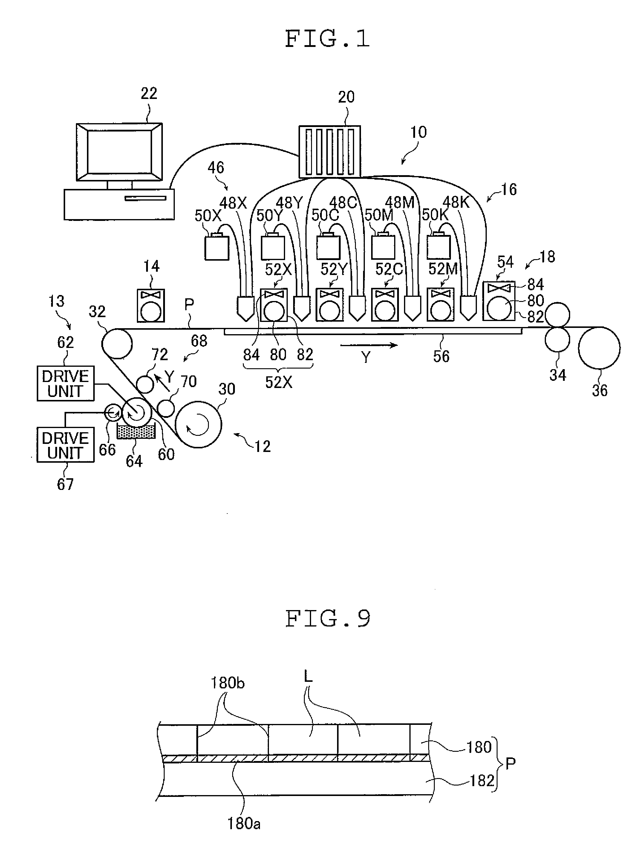
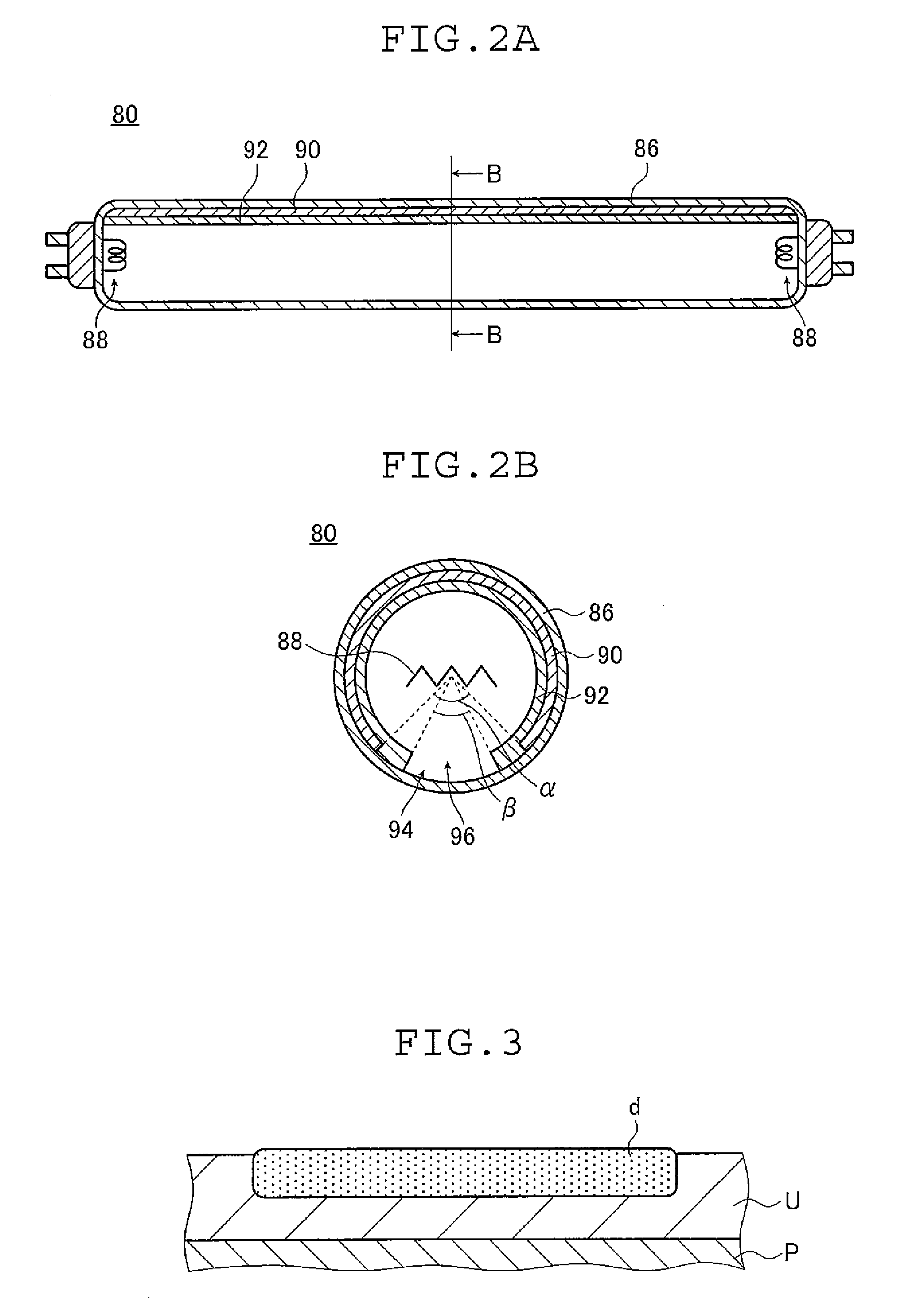
[0043]FIG. 1 is a front view schematically showing the structure of an embodiment of an ink-jet recording device according to the invention; FIG. 2A is a longitudinal sectional view schematically showing the structure of an exemplary fluorescent lamp used in UV irradiation units of the ink-jet recording device shown in FIG. 1; and FIG. 2B is a sectional view, taken along the line B-B, of the fluorescent lamp shown in FIG. 2A.

[0044]In the embodiments described below, active light-curable ink-jet recording devices which use an ultraviolet light-curable ink (UV-curable ink) as the active light-curable ink (also referred to as “active energy ray-curable ink”) that cures under irradiation with active light (also referred to as “active energy rays”) are described below. However, the invention is not limited to this and may apply to...


PUM


Abstract

The ink-jet recording device includes an image forming section where an active energy ray-curable ink is ejected onto a recording medium to form an image, and an image curing section which includes at least one light irradiation unit having a fluorescent lamp and which cures the ink on the recording medium upon exposure to active energy rays. The fluorescent lamp has a bulb, a reflective film formed on a bulb inner wall and having a first aperture formed on a recording medium side, and a phosphor film formed on the reflective film and the bulb inner wall and having a second aperture formed on the recording medium side. The formulas: β<α, 60°≦α≦150° and 30°≦β≦90° where α represents a first aperture angle of the first aperture and β represents a second aperture angle of the second aperture are satisfied.

Description

[0001]The entire contents of all documents cited in this specification are incorporated herein by reference.BACKGROUND OF THE INVENTION[0002]The present invention belongs to the field of ink-jet recording, and more specifically relates to an ink-jet recording device with which ink that cures upon exposure to active rays is ejected onto a recording medium to form an image thereon.[0003]One method of forming images on a recording medium involves image formation by ejecting ink droplets from an ink-jet head.[0004]An exemplary device for forming an image with an ink-jet head includes an ink-jet recording device in which an active energy ray-curable ink that cures upon exposure to active energy rays is ejected from an ink-jet head onto a recording medium and is cured by exposure to the active energy rays. Such ink-jet recording device using an active energy ray-curable ink has various advantages: It is an environmentally-friendly device; high-speed recording on various recording media is...

Claims


Application Information

Patent Timeline
Patent Type & Authority Applications(United States)
IPC IPC(8): B41J2/01
CPCB41J11/002B41J11/00214B41J11/00218
Inventor YOKOTA, YASUYO
Owner FUJIFILM CORP
Why Eureka
Try Eureka