

Image Forming Apparatus and Image Forming System
a technology of image forming apparatus and image forming system, which is applied in the direction of digital output to print units, instruments, digital computers, etc., can solve the problem of difficult for other people than programmers to change the source file, and achieve the effect of easy execution of complex customization
- Summary
- Abstract
- Description
- Claims
- Application Information
AI Technical Summary
Benefits of technology
Problems solved by technology
Method used
Image

Examples
embodiment 1
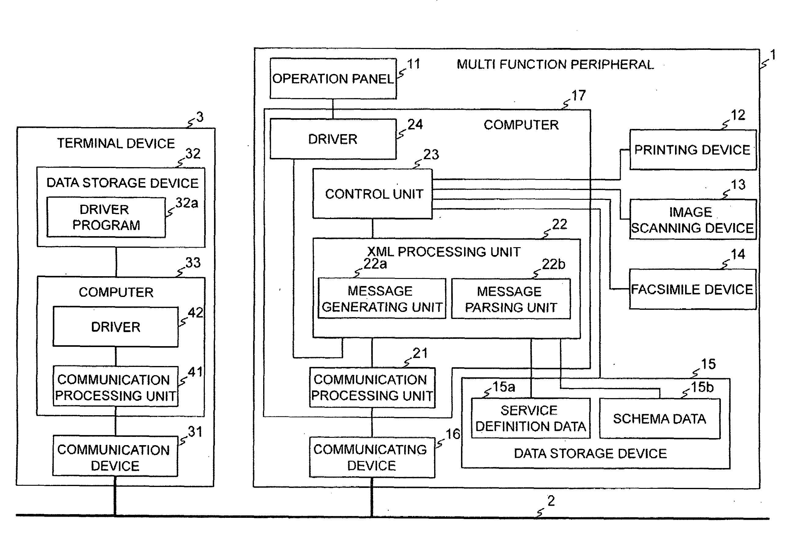
[0101]FIG. 1 shows a block diagram that indicates an image forming system including a multi function peripheral as an image forming apparatus according to Embodiment 1 of the present invention. In the system, a multi function peripheral 1 is connected to a computer network 2, and is used by either a terminal device 3 connected to the computer network 2 or a user who operates an operation panel 11 of the multi function peripheral 1. A user operation takes place to request to execute a service, and then a request message and a response message are transmitted either inside the multi function peripheral 1 or between the multi function peripheral 1 and the terminal device 3.
[0102]In FIG. 1, the multi function peripheral 1 has the operation panel 11, a printing device 12, an image scanning device 13, a facsimile device 14, a data storage device 15, a communicating device 16 and a computer 17.
[0103]The operation panel 11 is a user interface device that contains (a) a display device such a...
embodiment 2
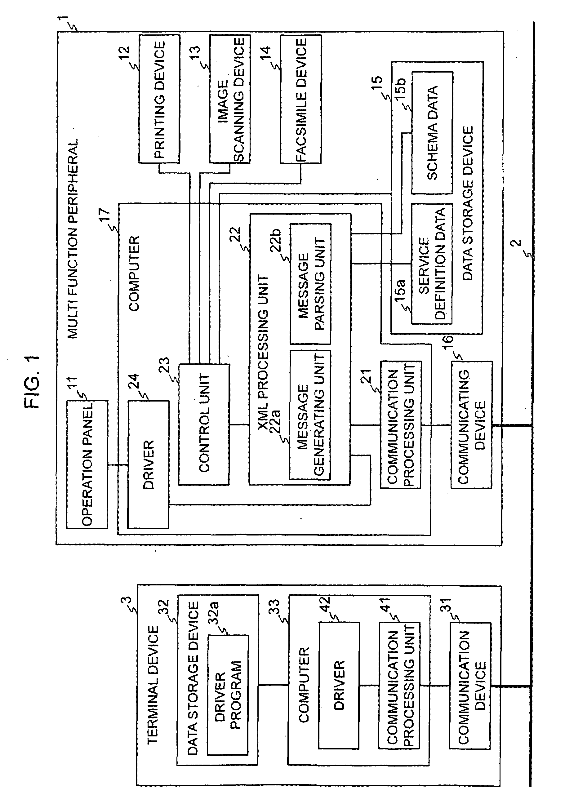
[0145]FIG. 7 shows a block diagram that indicates an image forming system including a multi function peripheral as an image forming apparatus according to Embodiment 2 of the present invention. In the system, a multi function peripheral 101 is connected to a computer network 102, and is used by either a terminal device 103 connected to the computer network 102 or a user who operates an operation panel 111 of the multi function peripheral 101. A user operation takes place to request to perform a service, and then a request message and a response message are transmitted either inside the multi function peripheral 101 or between the multi function peripheral 101 and the terminal device 103.
[0146]In FIG. 7, the multi function peripheral 101 has the operation panel 111, a printing device 112, an image scanning device 113, a facsimile device 114, a data storage device 115, a communicating device 116, and a computer 117.
[0147]The operation panel 111 is a user interface device that contains...
embodiment 3
[0209]As well as Embodiment 2, in Embodiment 3, buttons are displayed in an operation panel of an image forming apparatus, and attribution information on the buttons is described in a text format. In terms of a simple text language processing program, the attribution information in a text format is parsed, the buttons are displayed according to the attribution information, and a process specified by the attribution information is executed when the buttons are operated.
[0210]FIG. 26 shows a schematic diagram that indicates a hardware configuration in the image forming apparatus 210 of Embodiment 3.
[0211]In the image forming apparatus 210, an MPU 211 is connected via interfaces 212 to a PROM 213, a DRAM 214, an operation panel 215, a printer 216, a scanner 217, a NIC 218, a FAX modem 219, a USB port 220, a toner remaining amount detector 221, an IC card reader 222, an electronic tag reader 223, and a timer TM. In FIG. 26, for simplicity, the interfaces are depicted as one block.
[0212]...
PUM
 Abstract
Description
Claims
Application Information